UPPER INSTRUMENT PANEL REMOVAL
PROCEDURE
PRECAUTION
Note:After turning the ignition switch off, waiting time may be required before disconnecting the cable from the negative (-) battery terminal. Therefore, make sure to read the disconnecting the cable from the negative (-) battery terminal notices before proceeding with work.
REMOVE COMBINATION METER ASSEMBLY
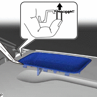
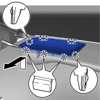
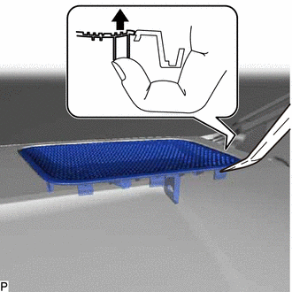
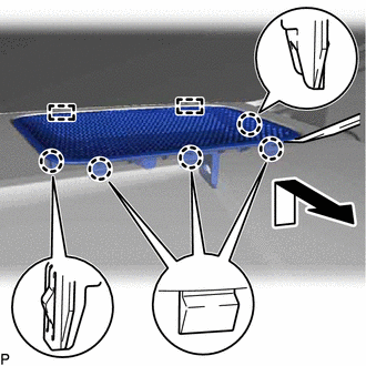
REMOVE NO. 1 INSTRUMENT PANEL GARNISH SUB-ASSEMBLY
-
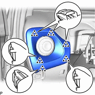
Disengage the 6 clips and remove the No. 1 instrument panel garnish sub-assembly.
-
REMOVE CENTER INSTRUMENT CLUSTER FINISH PANEL SUB-ASSEMBLY
-
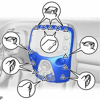
Disengage the 2 claws and 10 clips.
Disconnect each connector and remove the center instrument cluster finish panel sub-assembly.
-
REMOVE INSTRUMENT CLUSTER FINISH PANEL SUB-ASSEMBLY
-
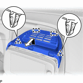
Disengage the 2 clips and 2 guides and remove the instrument cluster finish panel sub-assembly as shown in the illustration.
-
REMOVE GLOVE COMPARTMENT DOOR ASSEMBLY
-
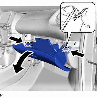
*a
Stopper
Slightly push it stoppers (A) and (B) in the directions indicated by the arrows in the illustration and pull down the glove compartment door assembly until the stoppers are disengaged.
-
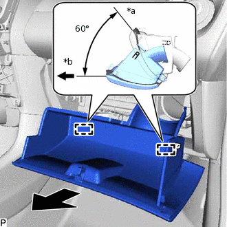
*a
Closed
*b
Open Approximately 60°
Open the glove compartment door assembly to approximately 60° from its closed position. Pull it horizontally in the direction indicated by the arrow to disengage the 2 hinges and remove the glove compartment door assembly.
Note:Pulling the glove compartment door assembly upward to remove it will cause the hinges to deform. Be sure to pull out the glove compartment door assembly horizontally.
-
REMOVE NO. 2 INSTRUMENT PANEL GARNISH SUB-ASSEMBLY
-
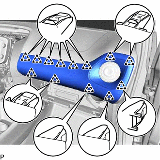
Disengage the 13 clips and remove the No. 2 instrument panel garnish sub-assembly.
-
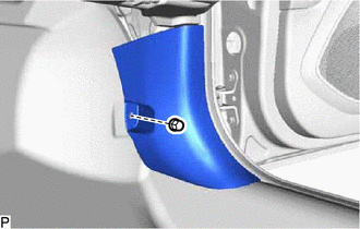
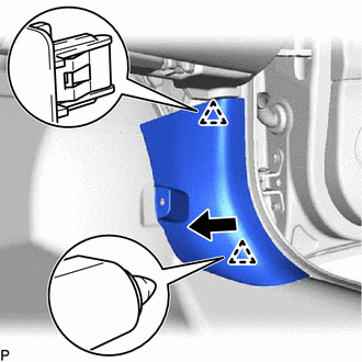
REMOVE COWL SIDE TRIM SUB-ASSEMBLY LH
-
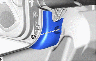
Remove the clip.
-
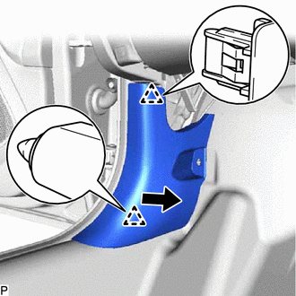
Disengage the 2 clips as shown in the illustration to remove the cowl side trim sub-assembly LH.
-
REMOVE FRONT DOOR OPENING TRIM WEATHERSTRIP LH
for 5 Door:Click here
for 3 Door:Click hereClick here
REMOVE FRONT PILLAR GARNISH LH
REMOVE NO. 1 INSTRUMENT PANEL SPEAKER PANEL SUB-ASSEMBLY
-
Using a finger, push the pin of the No. 1 instrument panel speaker panel sub-assembly to raise it and insert a moulding remover into the gap as shown in the illustration.
-
Using a moulding remover, disengage the 5 claws and 2 guides as shown in the illustration.
Disconnect the connector and remove the No. 1 instrument panel speaker panel sub-assembly.
-
REMOVE COWL SIDE TRIM BOARD RH
-
Remove the clip.
-
Disengage the 2 clips as shown in the illustration to remove the cowl side trim board RH.
-
REMOVE FRONT DOOR OPENING TRIM WEATHERSTRIP RH
Tip:Use the same procedure as for the LH side.
REMOVE FRONT PILLAR GARNISH RH
Tip:Use the same procedure as for the LH side.
REMOVE NO. 2 INSTRUMENT PANEL SPEAKER PANEL SUB-ASSEMBLY
-
Using a finger, push the pin of the No. 2 instrument panel speaker panel sub-assembly to raise it and insert a moulding remover into the gap as shown in the illustration.
-
Using a moulding remover, disengage the 5 claws and 2 guides as shown in the illustration.
Disconnect the connector and remove the No. 2 instrument panel speaker panel sub-assembly.
-
DISCONNECT INSTRUMENT PANEL PASSENGER AIRBAG CONNECTOR
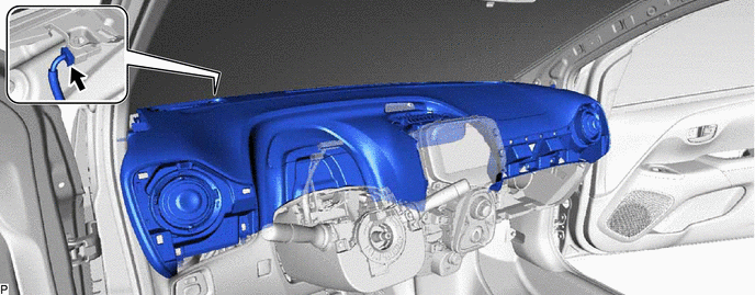
REMOVE UPPER INSTRUMENT PANEL ASSEMBLY
Disconnect the connector.
Remove the bolt <A>, 2 screws <B> and 2 clips.
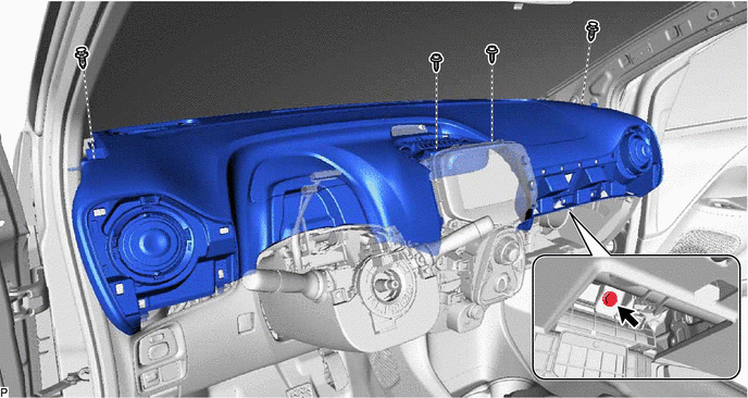
Pull the upper instrument panel assembly in the direction indicated by the arrow (1) to disengage the 7 clips.
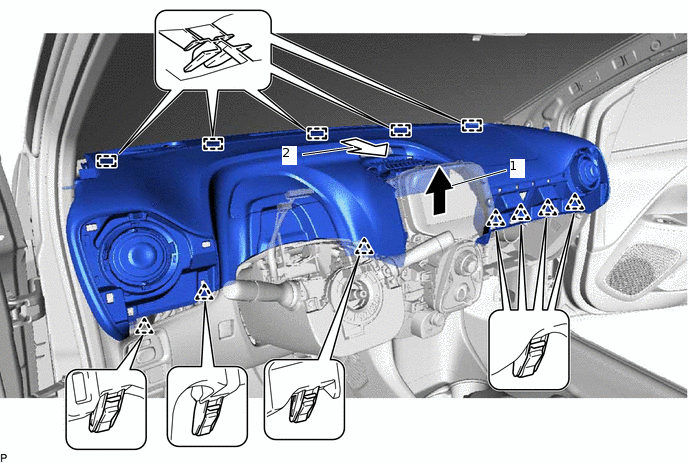
Pull the upper instrument panel assembly in the direction indicated by the arrow (2) to disengage the 5 guides and remove the upper instrument panel assembly.