ENGINE ASSEMBLY INSTALLATION
CAUTION / NOTICE / HINT
The engine assembly with transaxle is very heavy. Be sure to follow the procedure described in the repair manual, or the engine lifter may suddenly drop.
PROCEDURE
INSTALL ENGINE HANGER
REMOVE ENGINE FROM ENGINE STAND
Remove the engine assembly from the engine stand.
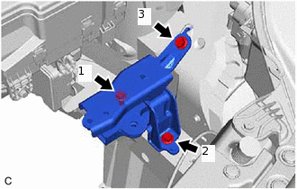
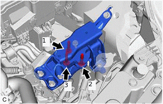
INSTALL ENGINE MOUNTING INSULATOR LH
 Tip:
Tip:Perform this procedure only when replacement of the engine mounting insulator LH is necessary.
Temporarily install the engine mounting insulator LH with the 3 bolts.
Fully tighten the 3 bolts in the order shown in the illustration.
52 N*m
530 kgf*cm
38 ft.*lbf
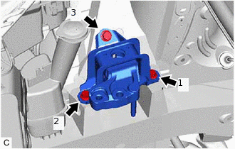
INSTALL ENGINE MOUNTING INSULATOR SUB-ASSEMBLY RH
 Tip:
Tip:Perform this procedure only when replacement of the engine mounting insulator sub-assembly RH is necessary.
Temporarily install the engine mounting insulator sub-assembly RH with the 3 bolts.
Fully tighten the 3 bolts in the order shown in the illustration.
52 N*m
530 kgf*cm
38 ft.*lbf
INSTALL FLYWHEEL SUB-ASSEMBLY
INSTALL CLUTCH DISC ASSEMBLY
INSTALL CLUTCH COVER ASSEMBLY
INSPECT AND ADJUST CLUTCH COVER ASSEMBLY
INSTALL FLYWHEEL HOUSING UNDER COVER
Install the flywheel housing under cover to the oil pan sub-assembly.
INSTALL ENGINE ASSEMBLY
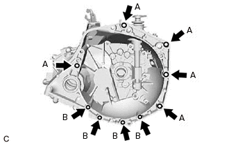
Align the input shaft with the clutch disc assembly and install the engine assembly to the transaxle.
Install the 9 bolts.
Bolt (A)
64 N*m
653 kgf*cm
47 ft.*lbf
Bolt (B)
39 N*m
398 kgf*cm
29 ft.*lbf
Note:Insert knock pins into the knock pin holes securely so that the end face of the transaxle fits close against the engine before tightening the bolts.
INSTALL NO. 1 DRIVE SHAFT HEAT INSULATOR
-
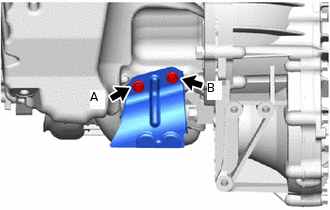
Install the No. 1 drive shaft heat insulator the engine assembly with the 2 bolts.
23.5 N*m
240 kgf*cm
17 ft.*lbf
Note:Temporarily tighten the bolt (A), and then fully tighten the 2 bolts in the order of (B) and (A).
-
INSTALL STARTER ASSEMBLY
w/ Stop And Start System:Click here
w/o Stop And Start System:Click here
INSTALL ENGINE WIRE
Install the engine wire to the engine assembly.
INSTALL ENGINE ASSEMBLY WITH TRANSAXLE
Set the engine assembly with transaxle on an engine lifter.
Note:Using height adjustment attachments and plate lift attachments, place the engine assembly with transaxle horizontally.
Operate the engine lifter and lift the engine assembly with transaxle to the position where the engine mounting insulator sub-assembly RH and engine mounting insulator LH can be installed.
CAUTION:Do not raise the engine assembly with transaxle more than necessary. If the engine assembly with transaxle is raised excessively, the vehicle may also be lifted up.
Note:Make sure that the engine assembly with transaxle is clear of all wiring and hoses.
While raising the engine assembly with transaxle into the vehicle, do not allow it to contact the vehicle.
-
Temporarily install the engine mounting insulator LH with the 3 bolts.
Fully tighten the 3 bolts in the order shown in the illustration.
52 N*m
530 kgf*cm
38 ft.*lbf
Install the engine mounting insulator sub-assembly RH with the 2 bolts and nut.
52 N*m
530 kgf*cm
38 ft.*lbf
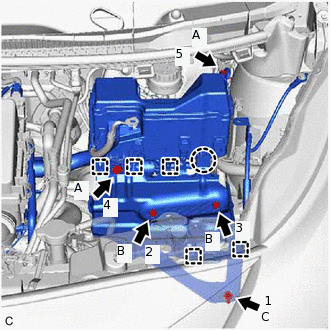
By inserting SST into the datum holes in the front suspension crossmember RH and LH alternately, tighten the bolts (A), (B) and (C) on both sides to the specified torque in several steps.
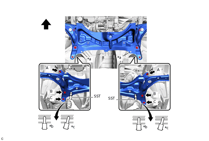
*a
Datum Hole
*b
Correct
*c
Incorrect
-
-

Front of the Vehicle
-
-
09670-00011
Bolt (A)
85 N*m
867 kgf*cm
63 ft.*lbf
Bolt (B)
134 N*m
1366 kgf*cm
99 ft.*lbf
Bolt (C)
48 N*m
489 kgf*cm
35 ft.*lbf
Note:Insert SST into the datum hole vertically.
If impossible to insert SST vertically, loosen all bolts and then insert SST again.
Lower the engine lifter.
REMOVE ENGINE HANGER
INSTALL FRONT EXHAUST PIPE ASSEMBLY
INSTALL FRONT DRIVE SHAFT ASSEMBLY
INSTALL NO. 1 STEERING COLUMN HOLE COVER SUB-ASSEMBLY
INSTALL NO. 2 STEERING INTERMEDIATE SHAFT ASSEMBLY
INSTALL STEERING COLUMN HOLE COVER PLATE
CONNECT CLUTCH RELEASE CABLE ASSEMBLY
for C550:Click here
for C551:Click here
CONNECT TRANSMISSION CONTROL CABLE ASSEMBLY
for C550:Click here
for C551:Click here
INSTALL AIR CLEANER FILTER ELEMENT SUB-ASSEMBLY
Install the air cleaner filter element sub-assembly to the cylinder head cover sub-assembly.
INSTALL INTAKE MANIFOLD
CONNECT ENGINE WIRE
Install the bolt and connect the No. 3 engine wire to the vehicle body.
8.4 N*m
86 kgf*cm
74 in.*lbf
Engage the 2 claws and connect the wire harness to the No. 1 engine room relay block.
Install the nut.
8.4 N*m
86 kgf*cm
74 in.*lbf
Connect the 2 connectors to the No. 1 engine room relay block.
Install the No. 1 engine room relay block cover.
Engage the wire harness clamp. (for LHD)
-
Connect the ECM connector and lower the lever.
Note:When connecting the ECM connector, make sure that dirt, water or other foreign matter does not contact the connecting parts of the ECM connector.
Be sure to securely connect the ECM connector.
CONNECT NO. 2 RADIATOR HOSE
Connect the No. 2 radiator hose to the water inlet and slide the clip to secure it.
CONNECT NO. 1 RADIATOR HOSE
Connect the No. 1 radiator hose to the cylinder head sub-assembly and slide the clip to secure it.
CONNECT INLET HEATER WATER HOSE
CONNECT OUTLET HEATER WATER HOSE
CONNECT NO. 1 FUEL VAPOR FEED HOSE
Connect the No. 1 fuel vapor feed hose to the purge valve (purge VSV) and slide the clip to secure it.
CONNECT FUEL TUBE SUB-ASSEMBLY
Connect the fuel tube connector to the fuel pipe.
CAUTION:Align the fuel tube connector with the fuel pipe, and push the fuel pipe into the fuel tube connector until the fuel tube connector makes a "click" sound. If it is difficult to push the fuel pipe into the fuel tube connector, apply a small amount of clean engine oil to the tip of the fuel pipe.
After connecting the fuel lines, check that the fuel pipe and fuel tube connector are securely connected by pulling on them.
Engage the claw and install the No. 1 fuel pipe clamp.
INSTALL COMPRESSOR ASSEMBLY WITH PULLEY (w/ Air Conditioning System)
Temporarily install the compressor assembly with pulley with the 3 bolts.
Fully tighten the 3 bolts.
24.5 N*m
250 kgf*cm
18 ft.*lbf
Connect the connector.
INSTALL GENERATOR ASSEMBLY
for 80A Type:Click here
for 100A Type:Click here
INSTALL V-RIBBED BELT TENSIONER ASSEMBLY
-
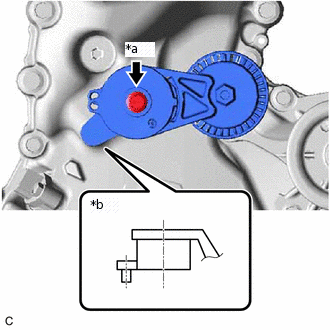
*a
Bolt
*b
Pin
Insert the rotation stopper pin to the timing chain cover sub-assembly.
Install the bolt.
54 N*m
551 kgf*cm
40 ft.*lbf
-
INSTALL V-RIBBED BELT
INSPECT V-RIBBED BELT
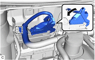
INSTALL BATTERY CLAMP SUB-ASSEMBLY
-
Engage the claw and install the battery clamp sub-assembly to the No. 1 engine room relay block.
Install the battery clamp sub-assembly with the 5 bolts in the order shown in the illustration.
Bolt (A)
8.4 N*m
86 kgf*cm
74 in.*lbf
Bolt (B)
7.4 N*m
75 kgf*cm
65 in.*lbf
Bolt (C)
17.2 N*m
175 kgf*cm
13 ft.*lbf
Engage the 5 wire harness clamps and connect the wire harness to the battery clamp sub-assembly.
-
INSTALL BATTERY
Install the battery to the battery clamp sub-assembly.
Install the No.2 battery clamp to the battery clamp sub-assembly with the bolt.
15.1 N*m
154 kgf*cm
11 ft.*lbf
Engage the 2 claws to connect the engine room main wire to the engine wire.
Install the engine room main wire with engine wire to the positive (+) battery terminal with the nut.
7.6 N*m
77 kgf*cm
67 in.*lbf
INSTALL INLET NO. 1 AIR CLEANER
Install the inlet No.1 air cleaner to the cylinder head cover sub-assembly.
CONNECT CABLE TO NEGATIVE BATTERY TERMINAL
Connect the cable to the negative (-) battery terminal.
5.4 N*m
55 kgf*cm
48 in.*lbf
Note:When disconnecting the cable, some systems need to be initialized after the cable is reconnected.
ADD ENGINE OIL
ADD ENGINE COOLANT
ADD MANUAL TRANSAXLE OIL
CHECK ENGINE OIL LEVEL
INSPECT AND ADJUST CLUTCH PEDAL SUB-ASSEMBLY
for LHD:Click here
for RHD:Click here
INSPECT FOR FUEL LEAK
INSPECT FOR COOLANT LEAK
INSPECT FOR OIL LEAK
INSPECT FOR EXHAUST GAS LEAK
INSTALL FRONT WHEELS
INSPECT IGNITION TIMING
INSPECT ENGINE IDLE SPEED
INSPECT CO/HC
ADJUST FRONT WHEEL ALIGNMENT
CHECK SPEED SENSOR SIGNAL
w/o VSC:Click here
w/ VSC:Click here