AUTOMATIC TRANSAXLE SYSTEM Shift Paddle Switch Circuit
| DTC Code | DTC Name |
|---|---|
| Shift Paddle Switch Circuit |
DESCRIPTION
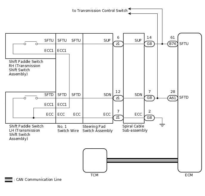
When the shift lever is in M, the shift range can be changed using the shift paddle switches. It is also possible to select the shift range when the vehicle is being driven with the shift lever in D by operating the shift paddle switches.
WIRING DIAGRAM
CAUTION / NOTICE / HINT
Refer to the inspection procedure for the CAN communication system.
If the CAN communication malfunctions, the TCM cannot receive current data from the ECM. In this case, the freeze frame data output from the TCM has not been updated, so the data will not be useful for the inspection. However, reading the Data List as the first step in troubleshooting is an effective way to find malfunctions.
The malfunctioning area can be confirmed using the Bus Check function of the GTS.
for LHD:
Click hereClick hereClick here
for RHD:
PROCEDURE
CHECK HARNESS AND CONNECTOR (SPIRAL CABLE - BODY GROUND)
-
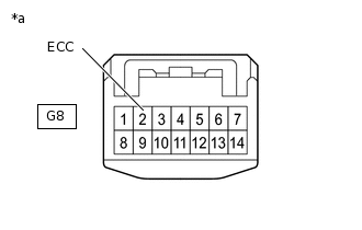
*a
Front view of wire harness connector
(to Spiral Cable Sub-assembly)
Disconnect the spiral cable connector.
Measure the resistance according to the value(s) in the table below.
Standard Resistance
Tester Connection
Condition
Specified Condition
G8-2 (ECC) - Body ground
Always
Below 1 Ω
Result
Proceed to
OK
NG
NG REPAIR OR REPLACE HARNESS OR CONNECTOR
-
INSPECT SPIRAL CABLE SUB-ASSEMBLY
Remove the spiral cable sub-assembly.
Measure the resistance according to the value(s) in the table below.
After setting the spiral cable to the center position, rotate the spiral cable 2.5 times clockwise and measure the resistance. Then rotate the spiral cable 2.5 times counterclockwise and measure the resistance.
After setting the spiral cable to the center position, rotate the spiral cable 2.5 times clockwise. Then while rotating the spiral cable 5 times counterclockwise, measure the resistance.
Standard Resistance
Tester Connection
Condition
Specified Condition
G8-14 (SUP) - z1-6 (SUP)
Always
Below 1 Ω
G8-7 (SDN) - z1-12 (SDN)
Always
Below 1 Ω
G8-2 (ECC) - z1-7 (ECC)
Always
Below 1 Ω
G8-14 (SUP) or z1-6 (SUP) - All other terminals
Always
10 kΩ or higher
G8-7 (SDN) or z1-12 (SDN) - All other terminals
Always
10 kΩ or higher
G8-2 (ECC) or z1-7 (ECC) - All other terminals
Always
10 kΩ or higher
Note:As the spiral cable may break, do not rotate the spiral cable more than the specified amount.
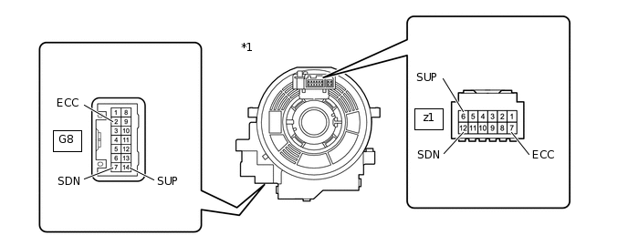
*1
Spiral Cable Sub-assembly
-
-
Result
Proceed to
OK
NG
INSPECT SHIFT PADDLE SWITCH LH (TRANSMISSION SHIFT SWITCH ASSEMBLY)
-
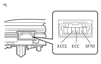
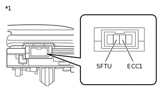
*1
Shift Paddle Switch LH
(Transmission Shift Switch Assembly)
Remove the shift paddle switch LH.
Measure the resistance according to the value(s) in the table below.
Standard Resistance
Tester Connection
Switch Condition
Specified Condition
SFTD - ECC
"-" shift paddle operated and held (down-shift)
Below 2.5 Ω
SFTD - ECC1
"-" shift paddle operated and held (down-shift)
Below 2.5 Ω
SFTD - ECC
"-" shift paddle not operated (down-shift)
1 MΩ or higher
SFTD - ECC1
"-" shift paddle not operated (down-shift)
1 MΩ or higher
Result
Proceed to
OK
NG
-
INSPECT SHIFT PADDLE SWITCH RH (TRANSMISSION SHIFT SWITCH ASSEMBLY)
-
*1
Shift Paddle Switch RH
(Transmission Shift Switch Assembly)
Remove the shift paddle switch RH.
Measure the resistance according to the value(s) in the table below.
Standard Resistance
Tester Connection
Switch Condition
Specified Condition
SFTU - ECC1
"+" shift paddle operated and held (up-shift)
Below 2.5 Ω
SFTU - ECC1
"+" shift paddle not operated (up-shift)
1 MΩ or higher
Result
Proceed to
OK
NG
-
INSPECT NO. 1 SWITCH WIRE
-
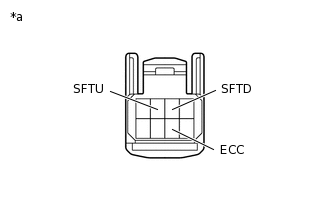
*a
No. 1 Switch Wire (Steering Pad Switch Side)
Disconnect the No. 1 switch wire connector.
Measure the resistance according to the value(s) in the table below.
Standard Resistance
Tester Connection
Switch Condition
Specified Condition
SFTD - ECC
"-" shift paddle operated and held (down-shift)
Below 2.5 Ω
SFTU - ECC
"+" shift paddle operated and held (up-shift)
Below 2.5 Ω
SFTD - ECC
"-" shift paddle not operated (down-shift)
1 MΩ or higher
SFTU - ECC
"+" shift paddle not operated (up-shift)
1 MΩ or higher
Result
Proceed to
OK
NG
-
INSPECT STEERING PAD SWITCH ASSEMBLY
-
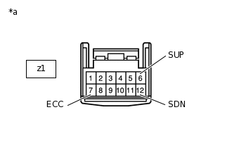
*a
Steering Pad Switch Assembly Connector (to Spiral Cable Sub-assembly)
Disconnect the steering pad switch assembly connector.
Measure the resistance according to the value(s) in the table below.
Standard Resistance
Tester Connection
Switch Condition
Specified Condition
z1-6 (SUP) - z1-7 (ECC)
"+" shift paddle operated and held (up-shift)
Below 2.5 Ω
z1-12 (SDN) - z1-7 (ECC)
"-" shift paddle operated and held (down-shift)
Below 2.5 Ω
z1-6 (SUP) - z1-7 (ECC)
"+" shift paddle not operated (up-shift)
1 MΩ or higher
z1-12 (SDN) - z1-7 (ECC)
"-" shift paddle not operated (down-shift)
1 MΩ or higher
Result
Proceed to
OK
NG
-
INSPECT HARNESS AND CONNECTOR (SPIRAL CABLE - ECM)
-
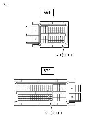
*a
Front view of wire harness connector
(to ECM)
Disconnect the ECM connectors.
Measure the resistance according to the value(s) in the table below.
Standard Resistance
Tester Connection
Condition
Specified Condition
B76-61 (SFTU) - Body ground
"+" shift paddle operated and held (up-shift)
Below 2.5 Ω
A61-28 (SFTD) - Body ground
"-" shift paddle operated and held (down-shift)
Below 2.5 Ω
B76-61 (SFTU) - Body ground
"+" shift paddle not operated (up-shift)
1 MΩ or higher
A61-28 (SFTD) - Body ground
"-" shift paddle not operated (down-shift)
1 MΩ or higher
Result
Proceed to
OK
NG
NG REPAIR OR REPLACE HARNESS OR CONNECTOR
-