ТОПЛИВНАЯ ФОРСУНКА СНЯТИЕ

CAUTION / NOTICE / HINT
The necessary procedures (adjustment, calibration, initialization, or registration) that must be performed after parts are removed, installed, or replaced during the fuel injector assembly removal/installation are shown below.
| Replacement Part or Procedure | Necessary Procedures | Effects/Inoperative when not Performed | Link |
|---|---|---|---|
| Battery terminal is disconnected/reconnected | Drive the vehicle until stop and start control is permitted (approximately 5 to 60 minutes) | Stop and start system | |
| Memorize steering angle neutral point | Panoramic view monitor system | ||
| Initialize back door lock | Power door lock control system | ||
| Initialize servo motor | Air conditioning system | ||
| Reset slide door close position | Power slide door system | ||
| Reset back door close position | Power back door system | ||
| Replacement of fuel injector assembly | Inspection After Repair |
|
PROCEDURE
-
PRECAUTION
Note
After turning the engine switch off, waiting time may be required before disconnecting the cable from the negative (-) battery terminal. Therefore, make sure to read the disconnecting the cable from the negative (-) battery terminal notices before proceeding with work.
-
DISCHARGE FUEL SYSTEM PRESSURE
-
DISCONNECT CABLE FROM NEGATIVE BATTERY TERMINAL
Note
When disconnecting the cable, some systems need to be initialized after the cable is reconnected.
-
REMOVE WINDSHIELD WIPER MOTOR AND LINK ASSEMBLY
-
SEPARATE BRAKE MASTER CYLINDER RESERVOIR ASSEMBLY
-
REMOVE NO. 1 HEATER AIR DUCT SPLASH SHIELD SEAL
-
REMOVE NO. 2 HEATER AIR DUCT SPLASH SHIELD SEAL
-
REMOVE OUTER COWL TOP PANEL SUB-ASSEMBLY
-
REMOVE AIR CLEANER CAP SUB-ASSEMBLY
-
REMOVE AIR CLEANER CASE SUB-ASSEMBLY
-
REMOVE AIR CLEANER HOSE ASSEMBLY
-
DISCONNECT FUEL TUBE SUB-ASSEMBLY
Note
Remove any foreign matter on the fuel tube connector and fuel pipe before performing this work.
-
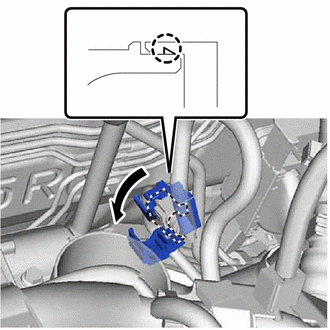
Disengage the claw to open the cover of the No. 1 fuel pipe clamp.
Note
Do not remove the No. 1 fuel pipe clamp from the fuel tube connector.
-
Check that there is no foreign matter around the fuel tube connector before disconnecting it. Clean it if necessary.
-
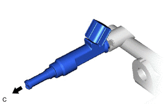
Disconnect the fuel tube sub-assembly from the fuel pipe.
-
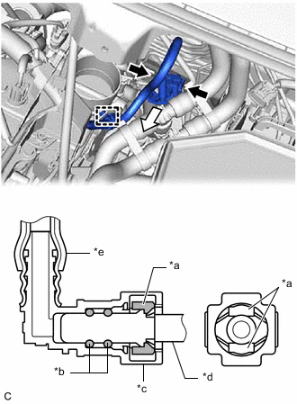
*a Retainer *b O-ring *c Fuel Tube Connector *d Fuel Pipe *e Nylon Tube 
Pinch 
Pull Pinch the retainer of the fuel tube connector, and then pull the fuel tube connector off of the fuel pipe.
Note
Be sure to disconnect the fuel tube connector by hand.
-
If the fuel tube connector and fuel pipe are stuck, push and pull the fuel tube connector to release it. Pull the fuel tube connector off of the fuel pipe carefully.
Note
-
Be sure to disconnect the fuel tube connector by hand.
-
Do not scratch or allow any foreign matter to get on the parts when disconnecting them as the fuel tube connector has O-rings that seal the pipe (fuel pipe).
-
Do not bend, twist, pinch or kink the nylon tube.
-
-
Check that there is no foreign matter on the sealing surfaces of the disconnected fuel lines. Clean them if necessary.
-
Cover the disconnected fuel pipe and fuel tube connector with plastic bags to prevent damage and contamination.
-
-
Disengage the clamp to disconnect the fuel tube sub-assembly from the fuel hose clamp.
-
-
REMOVE VACUUM SWITCHING VALVE ASSEMBLY (for ACIS)
-
DISCONNECT ENGINE WIRE
-
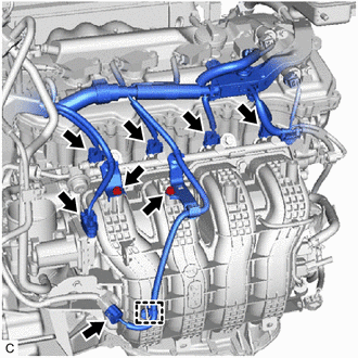
Disconnect the 4 fuel injector assembly connectors, throttle body with motor assembly connector and sensor wire connector.
-
Remove the 2 bolts and separate the 2 wire harness brackets from the intake manifold.
-
Disengage the clamp to disconnect the engine wire.
-
-
REMOVE FUEL DELIVERY PIPE
-
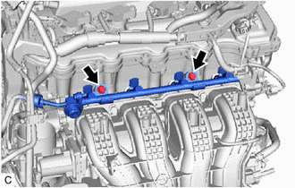
Remove the 2 bolts and fuel delivery pipe with the 4 fuel injector assemblies.
Note
Be careful not to drop the fuel injector assemblies when removing the fuel delivery pipe.
-
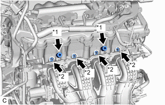
*1 Fuel Delivery Spacer *2 Injector Vibration Insulator Remove the 2 fuel delivery spacers from the cylinder head sub-assembly.
-
Remove the 4 injector vibration insulators from the cylinder head sub-assembly.
-
-
REMOVE FUEL INJECTOR ASSEMBLY
-
Pull the 4 fuel injector assemblies out of the fuel delivery pipe.
-
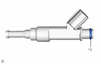
*1 O-ring Remove the O-ring from each fuel injector assembly.
-
Attach a tag or label with the corresponding cylinder number to each fuel injector assembly so that they can be installed to their original locations.
Note
Cover the fuel injector assemblies with plastic bags to prevent damage and contamination.
-