SFI SYSTEM(w/ Canister Pump Module), Diagnostic DTC:P013616, P013A7C, P013C7C, P015616
| DTC Code | DTC Name |
|---|---|
| P013616 | A/F (O2) Sensor Circuit Bank 1 Sensor 2 Circuit Current (Voltage) Below Threshold |
| P013A7C | A/F Sensor - Rich to Lean Bank 1 Sensor 2 Slow Response |
| P013C7C | A/F Sensor - Rich to Lean Bank 2 Sensor 2 Slow Response |
| P015616 | A/F (O2) Sensor Circuit Bank 2 Sensor 2 Circuit Current (Voltage) Below Threshold |
DESCRIPTION
Refer to DTC P003612.
| DTC No. | Detection Item | DTC Detection Condition | Trouble Area | MIL | Memory | Note |
|---|---|---|---|---|---|---|
| P013616 | A/F (O2) Sensor Circuit Bank 1 Sensor 2 Circuit Current (Voltage) Below Threshold | Either of the following conditions is met (2 trip detection logic).
|
|
Comes on | DTC stored | SAE: P0136 |
| P013A7C | A/F Sensor - Rich to Lean Bank 1 Sensor 2 Slow Response | During a fuel cut, the amount of time it takes for the current of the air fuel ratio sensor (bank 1 sensor 2) to increase to a certain amount is equal to or greater than the threshold (1 trip detection logic). |
|
Comes on | DTC stored | SAE: P013A |
| P013C7C | A/F Sensor - Rich to Lean Bank 2 Sensor 2 Slow Response | During a fuel cut, the amount of time it takes for the current of the air fuel ratio sensor (bank 2 sensor 2) to increase to a certain amount is equal to or greater than the threshold (1 trip detection logic). |
|
Comes on | DTC stored | SAE: P013C |
| P015616 | A/F (O2) Sensor Circuit Bank 2 Sensor 2 Circuit Current (Voltage) Below Threshold | Either of the following conditions is met (2 trip detection logic).
|
|
Comes on | DTC stored | SAE: P0156 |
MONITOR DESCRIPTION
-
Active Air fuel Ratio Control
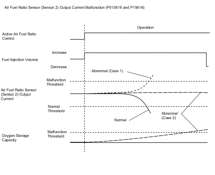
The ECM usually performs air fuel ratio feedback control so that the air fuel ratio sensors output indicates a near stoichiometric air fuel ratio. This vehicle includes active air fuel ratio control in addition to regular air fuel ratio control. The ECM performs active air fuel ratio control to detect any deterioration in the Three-Way Catalytic Converter (TWC) and any malfunctions of the air fuel ratio sensor (sensor 2) (refer to the diagram below).
Active air fuel ratio control is performed for approximately 30 seconds while driving with a warm engine. During active air fuel ratio control, the air fuel ratio is forcibly regulated to become lean or rich by the ECM. If the ECM detects a malfunction, a DTC is stored.
-
Abnormal Air Fuel Ratio Sensor (Sensor 2) Output Current (DTC P013616 and P015616)
Case 1: The ECM illuminates the MIL and stores a DTC when active rich air-fuel ratio control is being performed and the air fuel ratio sensor (sensor 2) current is 6 mA or more.
Case 2: The ECM illuminates the MIL and stores a DTC when active rich air-fuel ratio control is being performed, the oxygen storage capacity of the catalyst is more than 1.1 g and the air fuel ratio sensor (sensor 2) current is -0.25757 mA or more.
-
Abnormal Air Fuel Ratio Sensor (Sensor 2) Output Current During Fuel-cut from Rich Condition (DTC P013A7C and P013C7C)
During a fuel cut, if the amount of time it takes for the current of the air fuel ratio sensor (sensor 2) to increase to a certain amount is equal to or greater than the threshold, the responsiveness of the air fuel ratio sensor (sensor 2) is judged as degraded, the ECM illuminates the MIL and stores a DTC.
MONITOR STRATEGY
| Required Sensors/Components (Main) | Air fuel ratio sensor (sensor 2) |
| Required Sensors/Components (Related) | Crankshaft position sensor Engine coolant temperature sensor Mass air flow meter sub-assembly Throttle position sensor Air fuel ratio sensor (sensor 1) |
| Frequency of Operation | Once per driving cycle |
TYPICAL ENABLING CONDITIONS
| Battery voltage | 11 V or higher |
| Intake air temperature (mass air flow meter sub-assembly) | -10°C (14°F) or higher |
| Engine coolant temperature | 75°C (167°F) or higher |
| Atmospheric pressure | 76 kPa(abs) [11.02 psi(abs)] or higher |
| Idling | Off |
| Engine speed | Less than 3200 rpm |
| Air fuel ratio sensor (sensor 1) status | Activated |
| Fuel system status | Closed loop |
| Engine load | 10% or higher, and less than 140% |
| Battery voltage | 11 V or higher |
| Engine coolant temperature | 75°C (167°F) or higher |
| Catalyst temperature | 400°C (752°F) or higher |
| Fuel cut | On |
TYPICAL MALFUNCTION THRESHOLDS
| Both of the following conditions are met | A and B |
| A. Continuous time of active rich air fuel ratio control*1 | 0.5 seconds or more |
| *1: Target air fuel ratio | 14.3 or less |
| B. Either of the following conditions is met | (a) or (b) |
| (a) Air fuel ratio sensor (sensor 2) current | 6 mA or more |
| (b) OSC (Oxygen Storage Capacity) of catalyst | More than 1.1 g |
| The amount of time it takes for the current of the air fuel ratio sensor (sensor 2) to increase to a certain amount during a fuel cut (Normalized) | 1 or more |
CONFIRMATION DRIVING PATTERN
Tech Tips
-
This confirmation driving pattern is used for the "Perform Confirmation Driving Pattern" procedure of the following diagnostic troubleshooting procedure.
-
Performing this confirmation driving pattern will activate the air fuel ratio sensor (sensor 2) monitor (the catalyst monitor is performed simultaneously). This is very useful for verifying the completion of a repair.
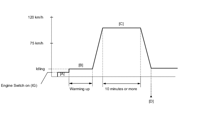
- P013616 and P015616
-
Connect the GTS to the DLC3.
-
Turn the engine switch on (IG).
-
Turn the GTS on.
-
Clear the DTCs (even if no DTCs are stored, perform the clear DTC procedure).
-
Turn the engine switch off and wait for at least 30 seconds.
-
Turn the engine switch on (IG) [A].
-
Turn the GTS on.
-
Start the engine and warm it up until the engine coolant temperature is 75°C (167°F) or higher [B].
-
Drive the vehicle at 75 to 120 km/h (46 to 75 mph) for 10 minutes or more [C].
CAUTION:
When performing the confirmation driving pattern, obey all speed limits and traffic laws.
-
Enter the following menus: Powertrain / Engine / Trouble Codes [D].
-
Read the pending DTCs.
Tech Tips
-
If a pending DTC is output, the system is malfunctioning.
-
If a pending DTC is not output, perform the following procedure.
-
-
Enter the following menus: Powertrain / Engine / Utility / All Readiness.
-
Input the DTC: P013616 or P015616.
-
Check the DTC judgment result.
GTS Display Description NORMAL
-
DTC judgment completed
-
System normal
ABNORMAL
-
DTC judgment completed
-
System abnormal
INCOMPLETE
-
DTC judgment not completed
-
Perform driving pattern after confirming DTC enabling conditions
Tech Tips
-
If the judgment result is NORMAL, the system is normal.
-
If the judgment result is ABNORMAL, the system is malfunctioning.
-
If the judgment result is INCOMPLETE, perform steps [C] through [D] again.
-
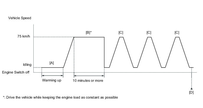
- P013A7C and P013C7C
-
Connect the GTS to the DLC3.
-
Turn the engine switch on (IG).
-
Turn the GTS on.
-
Clear the DTCs (even if no DTCs are stored, perform the clear DTC procedure).
-
Turn the engine switch off and wait for at least 30 seconds.
-
Turn the engine switch on (IG).
-
Turn the GTS on.
-
Start the engine and warm it up until the engine coolant temperature is 75°C (167°F) or higher [A].
-
Drive the vehicle at approximately 75 km/h (46 mph) for 10 minutes or more [B].
CAUTION:
When performing the confirmation driving pattern, obey all speed limits and traffic laws.
Tech Tips
Drive the vehicle while keeping the engine load as constant as possible.
-
Using the GTS, enter the following menus to check the fuel-cut status: Powertrain / Engine / Data List / Idle Fuel Cut.
-
With the shift state M, drive the vehicle at 75 km/h (46 mph), and then decelerate the vehicle by releasing the accelerator pedal for 5 seconds or more to perform the fuel-cut [C].
CAUTION:
When performing the confirmation driving pattern, obey all speed limits and traffic laws.
Tech Tips
While "Idle Fuel Cut" on the Data List is ON, fuel-cut control is being executed.
-
Repeat step [C] 2 times or more in one driving cycle.
-
Enter the following menus: Powertrain / Engine / Trouble Codes / Pending [D].
-
Read the pending DTCs.
Tech Tips
-
If a pending DTC is output, the system is malfunctioning.
-
If a pending DTC is not output, perform the following procedure.
-
-
Enter the following menus: Powertrain / Engine / Utility / All Readiness.
-
Input the DTC: P013A7C or P013C7C.
-
Check the DTC judgment result.
GTS Display Description NORMAL
-
DTC judgment completed
-
System normal
ABNORMAL
-
DTC judgment completed
-
System abnormal
INCOMPLETE
-
DTC judgment not completed
-
Perform driving pattern after confirming DTC enabling conditions
Tech Tips
-
If the judgment result is NORMAL, the system is normal.
-
If the judgment result is ABNORMAL, the system is malfunctioning.
-
If the judgment result is INCOMPLETE, drive the vehicle with the shift state M, and then perform step [C] again.
-
CAUTION / NOTICE / HINT
Tech Tips
Malfunctioning areas can be identified by performing the Active Test "Control the Injection Volume for A/F Sensor". This Active Test can help to determine whether the air fuel ratio sensors (sensor 1 and sensor 2) and other potential trouble areas are malfunctioning.
The following procedure describes how to perform the Active Test "Control the Injection Volume for A/F Sensor" using the GTS.
-
Connect the GTS to the DLC3.
-
Turn the engine switch on (IG).
-
Turn the GTS on.
-
Start the engine and warm it up until the engine coolant temperature is 75°C (167°F) or higher.
-
Warm up the air fuel ratio sensors at an engine speed of 2500 rpm for 90 seconds.
-
Enter the following menus: Powertrain / Engine / Active Test / Control the Injection Volume for A/F Sensor / Data List / A/F (O2) Sensor Current B1S1 and A/F (O2) Sensor Current B1S2 or A/F (O2) Sensor Current B2S1 and A/F (O2) Sensor Current B2S2.
-
Perform the Active Test with the engine idling (change the fuel injection volume).
-
Monitor the output current of the air fuel ratio sensor (sensor 1) (A/F (O2) Sensor Current B1S1 or A/F (O2) Sensor Current B2S1) and air fuel ratio sensor (sensor 2) (A/F (O2) Sensor Current B1S2 or A/F (O2) Sensor Current B2S2) displayed on the GTS.
Tech Tips
-
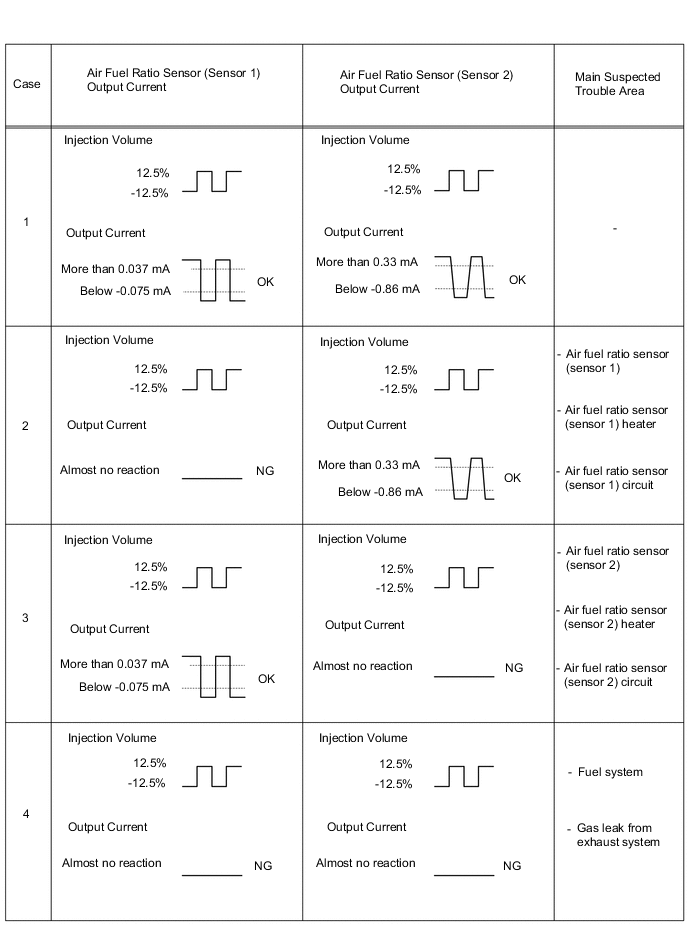
The Active Test "Control the Injection Volume for A/F Sensor" can be used to lower the fuel injection volume by 12.5% or increase the injection volume by 12.5%.
-
Each sensor reacts in accordance with the increase and decrease in the fuel injection volume.
| GTS Display (Sensor) | Injection Volume | Status | Current |
|---|---|---|---|
| A/F (O2) Sensor Current B1S1 A/F (O2) Sensor Current B2S1 (Air fuel ratio sensor (sensor 1)) |
12.5% | Rich | Below -0.075 mA |
| -12.5% | Lean | More than 0.037 mA | |
| A/F (O2) Sensor Current B1S2 A/F (O2) Sensor Current B2S2 (Air fuel ratio sensor (sensor 2)) |
12.5% | Rich | Below -0.86 mA |
| -12.5% | Lean | More than 0.33 mA |
Note
The air fuel ratio sensor (sensor 1) has an output delay of a few seconds and the air fuel ratio sensor (sensor 2) has a maximum output delay of approximately 20 seconds.
Performing the Active Test "Control the Injection Volume for A/F Sensor" allows the output value of the air fuel ratio sensors (sensor 1 and sensor 2) to be checked and graphed.
Note
Inspect the fuses for circuits related to this system before performing the following procedure.
Tech Tips
-
Read Freeze Frame Data using the GTS. The ECM records vehicle and driving condition information as Freeze Frame Data the moment a DTC is stored. When troubleshooting, Freeze Frame Data can help determine if the vehicle was moving or stationary, if the engine was warmed up or not, if the air fuel ratio was lean or rich, and other data from the time the malfunction occurred.
-
Sensor 1 refers to the sensor closest to the engine assembly.
-
Sensor 2 refers to the sensor farthest away from the engine assembly.
-
Bank 1 refers to the bank that includes the No. 1 cylinder*.
*: The No. 1 cylinder is the cylinder which is farthest from the transmission.
-
Bank 2 refers to the bank that does not include the No. 1 cylinder.
DTC Suspected Area P013616, P013A7C Bank 1 P015616, P013C7C Bank 2
PROCEDURE
-
READ OUTPUT DTC (DTC P013616, P013A7C, P013C7C OR P015616)
-
Connect the GTS to the DLC3.
-
Turn the engine switch on (IG).
-
Turn the GTS on.
-
Enter the following menus: Powertrain / Engine / Trouble Codes.
-
Read the DTCs.
Powertrain > Engine > Trouble CodesResult Result Proceed to DTC P013616 or P015616 is output A DTC P013A7C or P013C7C is output B DTC P013616, P013A7C, P013C7C or P015616 and other DTCs are output C Tech Tips
If any DTCs other than P013616, P013A7C, P013C7C or P015616 are output, troubleshoot those DTCs first.
B 
CHECK FOR EXHAUST GAS LEAK Click here
C 
GO TO DTC CHART Click here
A 
-
-
PERFORM ACTIVE TEST USING GTS (CONTROL THE INJECTION VOLUME FOR A/F SENSOR)
-
Connect the GTS to the DLC3.
-
Turn the engine switch on (IG).
-
Turn the GTS on.
-
Start the engine and warm it up until the engine coolant temperature reaches 75°C (167°F) or higher.
-
Warm up the air fuel ratio sensors at an engine speed of 2500 rpm for 90 seconds.
-
Enter the following menus: Powertrain / Engine / Active Test / Control the Injection Volume for A/F Sensor / Data List / A/F (O2) Sensor Current B1S1 and A/F (O2) Sensor Current B1S2 or A/F (O2) Sensor Current B2S1 and A/F (O2) Sensor Current B2S2.
Powertrain > Engine > Active TestActive Test Display Control the Injection Volume for A/F Sensor Data List Display A/F (O2) Sensor Current B1S1 A/F (O2) Sensor Current B2S1 A/F (O2) Sensor Current B1S2 A/F (O2) Sensor Current B2S2 -
Perform the Control the Injection Volume for A/F Sensor operation with the engine idling.
-
Monitor the output values of the air fuel ratio sensor (sensor 1) and air fuel ratio sensor (sensor 2) (A/F (O2) Sensor Current B1S1 and A/F (O2) Sensor Current B1S2 or A/F (O2) Sensor Current B2S1 and A/F (O2) Sensor Current B2S2) displayed on the GTS.
Tech Tips
-
The Control the Injection Volume for A/F Sensor operation lowers the fuel injection volume by 12.5% or increases the injection volume by 12.5%.
-
The air fuel ratio sensor (sensor 1) has an output delay of a few seconds and the air fuel ratio sensor (sensor 2) has a maximum output delay of approximately 20 seconds.
-
If the sensor output value does not change (almost no reaction) while performing the Active Test, the sensor may be malfunctioning.
-
With V type engines, when the sensor output values for both banks stay as either lean or rich, parts other than the sensor may be malfunctioning. Comparing the sensor output for both banks can be useful when troubleshooting.
Standard GTS Display (Sensor) Injection Volume Status Current A/F (O2) Sensor Current B1S1
A/F (O2) Sensor Current B2S1
(Air fuel ratio (sensor 1))
12.5% Rich Below -0.075 mA -12.5% Lean More than 0.037 mA A/F (O2) Sensor Current B1S2
A/F (O2) Sensor Current B2S2
(Air fuel ratio (sensor 2))
12.5% Rich Below -0.86 mA -12.5% Lean More than 0.33 mA Result Status of A/F (O2) Sensor Current B1S1 or A/F (O2) Sensor Current B2S1 Status of A/F (O2) Sensor Current B1S2 or A/F (O2) Sensor Current B2S2 Suspected Trouble Area Proceed to Lean/Rich Lean/Rich
-
Air fuel ratio sensor (sensor 2)
A Lean Lean
-
Gas leak from exhaust system
-
Extremely lean actual air fuel ratio
-
Air fuel ratio sensor (sensor 2)
B Rich Rich
-
Gas leak from exhaust system
-
Extremely rich actual air fuel ratio
-
Air fuel ratio sensor (sensor 2)
Lean/Rich Lean
-
Air fuel ratio sensor (sensor 2)
-
Gas leak from exhaust system
C Lean/Rich Rich
-
Air fuel ratio sensor (sensor 2)
-
Gas leak from exhaust system
Lean Lean/Rich
-
Air fuel ratio sensor (sensor 1)
-
Air fuel ratio sensor (sensor 2)
D Rich Lean/Rich
-
Air fuel ratio sensor (sensor 1)
-
Air fuel ratio sensor (sensor 2)
-
Lean: During the Control the Injection Volume for A/F Sensor Active Test, the air fuel ratio sensor (sensor 1) output current (A/F (O2) Sensor Current B1S1 or A/F (O2) Sensor Current B2S1) is consistently more than 0.037 mA, and the air fuel ratio sensor (sensor 2) output current (A/F (O2) Sensor Current B1S2 or A/F (O2) Sensor Current B2S2) is consistently more than 0.33 mA.
-
Rich: During the Control the Injection Volume for A/F Sensor Active Test, the air fuel ratio sensor (sensor 1) output current (A/F (O2) Sensor Current B1S1 or A/F (O2) Sensor Current B2S1) is consistently below -0.075 mA, and the air fuel ratio sensor (sensor 2) output current (A/F (O2) Sensor Current B1S2 or A/F (O2) Sensor Current B2S2) is consistently below -0.86 mA.
-
Lean/Rich: During the Control the Injection Volume for A/F Sensor Active Test, the output current of the air fuel ratio sensor (sensor 1) or air fuel ratio sensor (sensor 2) alternate correctly.
Tech Tips
Refer to "Data List / Active Test" [A/F (O2) Sensor Current B1S1, A/F (O2) Sensor Current B2S1, A/F (O2) Sensor Current B1S2 and A/F (O2) Sensor Current B2S2].
-
B
CHECK FOR EXHAUST GAS LEAK Click here
C
CHECK FOR EXHAUST GAS LEAK Click here
D
REPLACE AIR FUEL RATIO SENSOR (SENSOR 1) Click here
A
-
-
REPLACE AIR FUEL RATIO SENSOR (SENSOR 2)
-
Replace the air fuel ratio sensor (sensor 2).
Tech Tips
Perform "Inspection After Repair" after replacing the air fuel ratio sensor (sensor 2).
Result Proceed to NEXT
NEXT
-
-
CLEAR DTC
-
Connect the GTS to the DLC3.
-
Turn the engine switch on (IG).
-
Turn the GTS on.
-
Clear the DTCs.
Powertrain > Engine > Clear DTCs -
Turn the engine switch off and wait for at least 30 seconds.
Result Proceed to NEXT
NEXT
-
-
CONFIRM WHETHER MALFUNCTION HAS BEEN SUCCESSFULLY REPAIRED
-
Drive the vehicle in accordance with the driving pattern described in Confirmation Driving Pattern.
-
Enter the following menus: Powertrain / Engine / Utility / All Readiness.
Powertrain > Engine > UtilityTester Display All Readiness -
Input the DTC: P013616 or P015616.
-
Check the DTC judgment result.
Result GTS Display Description NORMAL
-
DTC judgment completed
-
System normal
ABNORMAL
-
DTC judgment completed
-
System abnormal
INCOMPLETE
-
DTC judgment not completed
-
Perform driving pattern after confirming DTC enabling conditions
Result Proceed to NEXT -
NEXT
END
-
-
CHECK FOR EXHAUST GAS LEAK
-
Check for exhaust gas leaks.
OK No gas leaks in exhaust system. Tech Tips
Perform "Inspection After Repair" after repairing or replacing the exhaust system.
Result Proceed to OK NG
NG
REPAIR OR REPLACE EXHAUST SYSTEM
OK
-
-
CHECK CAUSE OF EXTREMELY RICH OR LEAN ACTUAL AIR FUEL RATIO
-
Check the cause of extremely rich or lean actual air fuel ratio, referring to the DTC P017100, P017200, P017400 and P017500 Inspection Procedure.
Result Proceed to NEXT
NEXT
GO TO STEP 10 Click here
-
-
CHECK FOR EXHAUST GAS LEAK
-
Check for exhaust gas leaks.
OK No gas leaks in exhaust system. Tech Tips
-
Perform "Inspection After Repair" after repairing or replacing the exhaust system.
-
Perform "Inspection After Repair" after replacing the air fuel ratio sensor (sensor 2).
Result Proceed to OK NG -
OK
REPLACE AIR FUEL RATIO SENSOR (SENSOR 2) Click here
NG
REPAIR OR REPLACE EXHAUST SYSTEM
-
-
REPLACE AIR FUEL RATIO SENSOR (SENSOR 1)
-
Replace the air fuel ratio sensor (sensor 1).
Tech Tips
Perform "Inspection After Repair" after replacing the air fuel ratio sensor (sensor 1).
Result Proceed to NEXT
NEXT
-
-
CLEAR DTC
-
Connect the GTS to the DLC3.
-
Turn the engine switch on (IG).
-
Turn the GTS on.
-
Clear the DTCs.
Powertrain > Engine > Clear DTCs -
Turn the engine switch off and wait for at least 30 seconds.
Result Proceed to NEXT
NEXT
-
-
CHECK WHETHER DTC OUTPUT RECURS (DTC P013616 OR P015616)
-
Drive the vehicle in accordance with the driving pattern described in Confirmation Driving Pattern.
-
Enter the following menus: Powertrain / Engine / Utility / All Readiness.
Powertrain > Engine > UtilityTester Display All Readiness -
Input the DTC: P013616 or P015616.
-
Check that the DTC judgment result is NORMAL. If the DTC judgment result is INCOMPLETE, perform the confirmation drive pattern again but increase the vehicle speed.
Result Result Proceed to NORMAL
(DTCs are not output)
A ABNORMAL
(DTC P013616 or P015616 is output)
B Tech Tips
Perform "Inspection After Repair" after replacing the air fuel ratio sensor (sensor 2).
A
END
B
REPLACE AIR FUEL RATIO SENSOR (SENSOR 2) Click here
-
-
CHECK FOR EXHAUST GAS LEAK
-
Check for exhaust gas leaks.
OK No gas leaks in exhaust system. Tech Tips
Perform "Inspection After Repair" after repairing or replacing the exhaust system.
Result Proceed to OK NG
NG
REPAIR OR REPLACE EXHAUST SYSTEM
OK
-
-
CLEAR DTC
-
Connect the GTS to the DLC3.
-
Turn the engine switch on (IG).
-
Turn the GTS on.
-
Clear the DTCs.
Powertrain > Engine > Clear DTCs -
Turn the engine switch off and wait for at least 30 seconds.
Result Proceed to NEXT
NEXT
-
-
CHECK WHETHER DTC OUTPUT RECURS (DTC P013A7C OR P013C7C)
-
Drive the vehicle in accordance with the driving pattern described in Confirmation Driving Pattern.
-
Enter the following menus: Powertrain / Engine / Utility / All Readiness.
Powertrain > Engine > UtilityTester Display All Readiness -
Input the DTC: P013A7C or P013C7C.
-
Check that the DTC judgment result is NORMAL. If the DTC judgment result is INCOMPLETE, perform the confirmation drive pattern again but increase the vehicle speed.
Result Result Proceed to NORMAL
(DTCs are not output)
A ABNORMAL
(DTC P013A7C or P013C7C is output)
B Tech Tips
Perform "Inspection After Repair" after replacing the air fuel ratio sensor (sensor 2).
A
CHECK FOR INTERMITTENT PROBLEMS Click here
B
REPLACE AIR FUEL RATIO SENSOR (SENSOR 2) Click here
-