PANORAMIC VIEW MONITOR SYSTEM SYSTEM DESCRIPTION
-
GENERAL
-
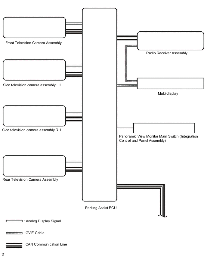
This system has front, passenger side, driver side and rear television camera assemblies mounted around the vehicle to display around the vehicle on the multi-display. The display panel also shows a composite view consisting of the area behind the vehicle and parking guidelines to assist the driver in parking the vehicle by monitoring the area around the vehicle.
-
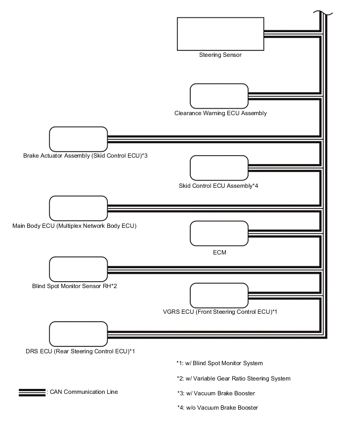
This system consists of the following components:
-
*1: w/ Blind Spot Monitor System
*2: w/ Variable Gear Ratio Steering System
*3: w/ Vacuum Brake Booster
*4: w/o Vacuum Brake Booster
-
Parking assist ECU
-
Panoramic view monitor main switch (integration control and panel assembly)
-
Rear television camera assembly
-
Front television camera assembly
-
Side television camera assembly LH
-
Side television camera assembly RH
-
Radio receiver assembly
-
Multi-display
-
Steering sensor
-
Brake actuator assembly (skid control ECU)*3
-
Skid control ECU assembly*4
-
Main body ECU (multiplex network body ECU)
-
Clearance warning ECU assembly
-
ECM
-
Blind spot monitor sensor RH*1
-
VGRS ECU (front steering control ECU)*2
-
DRS ECU (rear steering control ECU)*2
-
-
This system is equipped with a self-diagnosis system, which is operated from a designated window that appears on the display panel, just as in the audio and visual system*1 or navigation system*2.
-
*1: w/ Audio and Visual System
-
*2: w/ Navigation System
-
-
-
FUNCTION OF COMPONENTS
-
The parking assist ECU controls the system by using information from the following components.
Item Function Rear Television Camera Assembly
-
Mounted on the luggage compartment door to transmit the rear view of the vehicle to the parking assist ECU
-
Has a color video camera that uses a Complementary Metal Oxide Semiconductor (CMOS) and a wide-angle lens
Front Television Camera Assembly Generates a video feed showing the front side of the vehicle and transmits the video to the parking assist ECU Side Television Camera Assembly LH Generates a video feed showing the left side of the vehicle and transmits the video to the parking assist ECU Side Television Camera Assembly RH Generates a video feed showing the right side of the vehicle and transmits the video to the parking assist ECU Parking Assist ECU
-
Turns the panoramic view monitor system ON and OFF according to the display conditions, based on the received panoramic view monitor main switch signals, shift position signals, and vehicle speed signals
-
Sends the display request signals for the panoramic view and wide front view screen, panoramic view and side clearance view screen, panoramic view and rear view screen, panoramic view and wide rear view screen, see through view screen, or moving view screen to the radio receiver assembly according to the display conditions, based on the received panoramic view monitor main switch signals, shift position signals, and vehicle speed signals
-
Sends the display switching request signals for the panoramic view and wide front view screen, panoramic view and side clearance view screen, panoramic view and rear view screen, panoramic view and wide rear view screen, see through view screen, or moving view screen to the radio receiver assembly according to the display conditions, based on the received outer mirror retraction signals
-
Displays the composite image of the surrounding area images taken by each camera and the image calculated from vehicle status information such as the steering angle signals on the multi-display screen
-
Renders each configuration page in the diagnosis window and outputs the screen to the multi-display
-
Stops displaying the buttons and guidelines on the panoramic view and rear view monitor screen, or panoramic view and wide back view monitor screen when the screen is being displayed and a luggage compartment door open status signal is received
-
Stores each configuration setting from the diagnosis window
Panoramic View Monitor Main Switch (Integration Control and Panel Assembly) Sends switch operation signals to the parking assist ECU Radio Receiver Assembly Allows remote touch panel operations when the panoramic view monitor screen or diagnosis screen is displayed Steering Sensor Sends the steering angle signals and sensor status signals to the parking assist ECU via the CAN communication system Brake Actuator Assembly (Skid Control ECU)*3
Skid Control ECU Assembly*4
Sends the vehicle speed signals, drive type signals, and system status signals to the parking assist ECU via the CAN communication system ECM
-
Sends the engine model signals, and system status signals to the parking assist ECU via the CAN communication system
-
Sends the shift position signals to the parking assist ECU via the CAN communication system
Main Body ECU (Multiplex Network Body ECU)
-
Sends the luggage compartment door courtesy light switch signal to the parking assist ECU via the CAN communication system.
-
Sends the mirror retract request signal to the parking assist ECU via the CAN communication system
Clearance Warning ECU Assembly Sends information from each sonar via the CAN communication system Blind Spot Monitor Sensor*1 Transmits the RCTA information signal via CAN communication VGRS ECU (Front Steering Control ECU)*2 Transmits the VGRS relative angle signals to the parking assist ECU via CAN communication. DRS ECU (Rear Steering Control ECU)*2 Transmits the rear wheel angle angle signals to the parking assist ECU via CAN communication. *1: w/ Blind Spot Monitor system
*2: w/ Variable Gear Ratio Steering System
*3: w/ Vacuum Brake Booster
*4: w/o Vacuum Brake Booster
-
-
-
PANORAMIC VIEW SCREEN DISPLAY
-
See-through view screen
-
The entire area surrounding the vehicle is displayed.
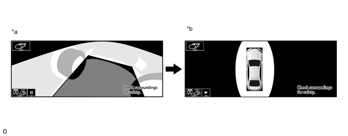
*a Vehicle interior view *b Upper view
-
-
Moving view screen
-
The entire area surrounding the vehicle is displayed.
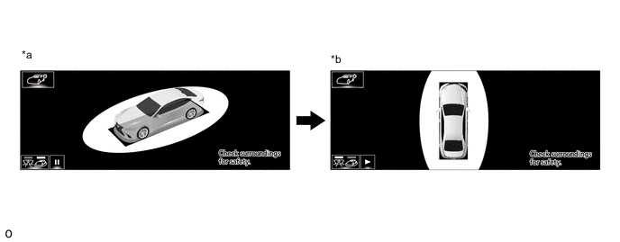
*a Slant upper view *b Upper view
-
-
Panoramic view and Cornering view screen
*a When turning left *b when turning right Panoramic view and Cornering view screen Description Signal Name Color (1) Front distance guide line Blue (2) Front wheel ground contact line Gray (3) Vehicle width parallel line Gray (4) Forward estimated course line Yellow -
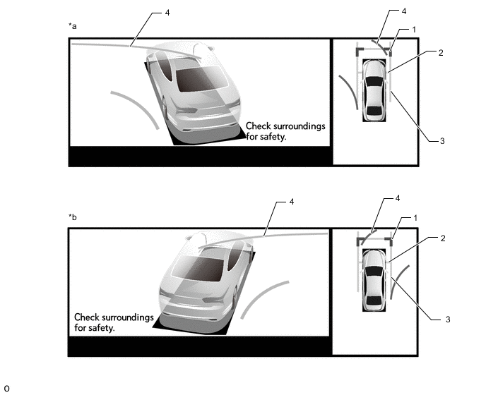
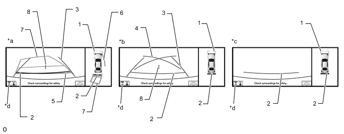
Panoramic view and wide front view screen
*a Estimated course line display mode *b Distance guide line display mode Panoramic View and Wide Front View Screen Description Signal Name Color Panoramic View and Wide Front View Screen Estimated course line display mode Distance guide line display mode (1) Front distance guide line Blue Displayed Displayed (2) Forward estimated course line Yellow Displayed Not displayed -
Panoramic View and Side Clearance View Screen
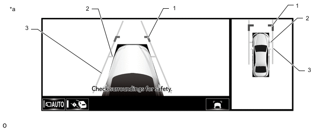
*a When the outer rear view mirror assembly is deployed. - - Panoramic View and Side Clearance View Screen Description Signal Name Color (1) Front distance guide line Blue (2) Front wheel ground contact line Gray (3) Vehicle width parallel line Gray -
Panoramic view and wide rear view screen
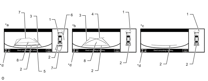
*a Estimated course line display mode *b Parking guide line display mode *c Distance guide line display mode *d Display mode switching button Tech Tips
The screen changes to the panoramic view and rear view screen when the display mode switch button or rear view screen is selected.
Panoramic View and Wide Rear View Screen Description Signal Name Color Panoramic View and Rear View Screen Estimated course line display mode Parking guide line display mode Distance guide line display mode (1) Front distance guide line Blue Displayed Displayed Displayed (2) Rear distance guide line Red/Yellow Displayed Displayed Displayed (3) Rear vehicle width extension line Blue Displayed Displayed Not displayed (4) Parking guide line Blue Not displayed Displayed Not displayed (5) Rear distance guide line Blue Displayed Not displayed Not displayed (6) Side estimated course line Yellow Displayed Not displayed Not displayed (7) Rear estimated course line Yellow Displayed Not displayed Not displayed (8) Vehicle center line Blue Displayed Displayed Displayed -
Panoramic view and rear view screen
*a Estimated course line display mode *b Parking guide line display mode *c Distance guide line display mode *d Display mode switching button Tech Tips
In the rear view screen, the screen display mode can be switched by pressing the guide line display mode switching button or rear view screen on the screen.
Panoramic View and Rear View Screen Description Signal Name Color Panoramic View and Rear View Screen Estimated course line display mode Parking guide line display mode Distance guide line display mode (1) Front distance guide line Blue Displayed Displayed Displayed (2) Rear distance guide line Red/Yellow Displayed Displayed Displayed (3) Rear vehicle width extension line Blue Displayed Displayed Not displayed (4) Parking guide line Blue Not displayed Displayed Not displayed (5) Rear distance guide line Blue Displayed Not displayed Not displayed (6) Side estimated course line Yellow Displayed Not displayed Not displayed (7) Rear estimated course line Yellow Displayed Not displayed Not displayed (8) Vehicle center line Blue Displayed Displayed Not displayed -
Side view screen
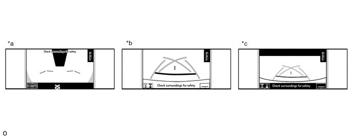
*a Side view and wide front view screen *b Side view and rear view screen *c Side view and wide rear view screen - - Tech Tips
Refer to the content of panoramic view and rear view screen and panoramic view and wide front view screen for information about the rear view and wide front view screens.
-
Rear camera detection function screen
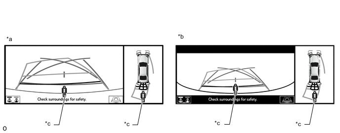
*a Side view and rear view screen *b Panoramic View and Wide Rear View Screen *c Rear Camera Detection Icon - -
-
-
PANORAMIC VIEW SCREEN DESCRIPTION
-
Manual display mode
-
When the Panoramic view monitor main switch (integration control and panel assembly) is pressed with the engine switch on (IG) or engine running, the panoramic view monitor system switches to a screen shown below according to the shift position
Figure 1. Screen Transition Chart (Manual Display Mode)
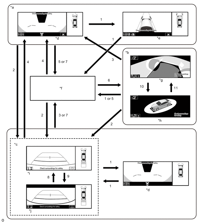
*a Shift position in any position other than P or R. *b Shift position in P and Lexus parking assist-sensor system on *c Shift position in R *d Panoramic view and wide front view screen *e Panoramic view and side clearance view screen *f Navigation screen, etc. *g See-through view screen *h Moving view screen *i Panoramic view and rear view screen *j Panoramic view and wide rear view screen Screen Transition Conditions (Manual Display Mode) No. Screen Transition Conditions (1) Panoramic view monitor main switch is pressed (2) Shift position is moved to R (3) Shift position is moved to other than P or R (4) Shift position is moved to other than P or R and operation (1) is performed (5) "MAP/VOICE" switches, etc. on the multi-display are pressed (6) Operation (1) is performed with the shift position in P (7) Shift position is moved to P (8) Switch image mode button or rear view screen is selected (9) Switch image mode button or wide rear view screen is selected (10) Moving view switch button is selected (11) See through view switch button is selected Tech Tips
If the panoramic view monitor main switch (integration control and panel assembly) is pressed at a vehicle speed of approximately 20 km/h (12 mph) or lower, the panoramic view monitor system screen is displayed. If the vehicle speed exceeds approximately 20 km/h (12 mph), the display switches to the navigation screen or information settings screen.
-
-
Screen transition chart (automatic display mode)
-
When the shift position is not in P or R, in addition to switching screens by pressing the panoramic view monitor main switch (integration control and panel assembly), the automatic display mode can be selected by pressing the automatic display mode switching button.
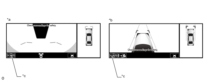
*a Panoramic view and wide front view screen *b Panoramic view and side clearance view screen *c Automatic display mode - - Automatic Display Mode Switching Button
(Indicator in Button)
Screen Switching Mode ON
(Illuminated)
Automatic display mode OFF
(Not illuminated)
Manual display mode Tech Tips
-
In the automatic display mode, press the panoramic view monitor main switch (integration control and panel assembly) or panel switch to switch screens in the same way as the manual display mode.
-
When switching to the navigation screen, etc. in the automatic display mode, the display switches to the screen that was displayed last. However, the display switches to the panoramic view and wide front view screen if the shift position is not in P or R after the engine switch is turned from off to on (IG).
-
-
The automatic display mode automatically switches the display according to the vehicle status.
Figure 2. Screen Transition Chart (Automatic Display Mode)
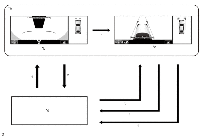
*a Shift position in any position other than P or R. *b Panoramic view and wide front view screen *c Panoramic view and side clearance view screen *d Navigation screen, etc. Screen Transition Conditions (Automatic Display Mode) No. Screen Transition Conditions (1) Panoramic view monitor main switch (integration control and panel assembly) is pressed (2) Current location switches, etc. on the multi-display are pressed (3) Vehicle speed changes from above approximately 20 km/h (12 mph) to approximately 20 km/h (12 mph) or lower. The screen that was last displayed is displayed on the multi-display.* (4) Vehicle speed changes from approximately 20 km/h (12 mph) or lower to above approximately 20 km/h (12 mph) *: The panoramic view and wide front view screen is the first screen displayed after the engine switch was turned off.
-
-
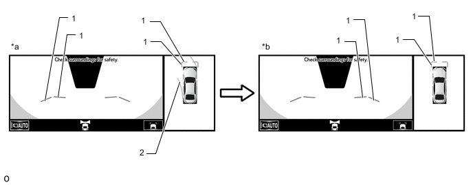
Panoramic View Zoom Function
-
When detail within the image on the panoramic view screen is too small and difficult to see, the user can magnify the image by selecting one of the 2 areas on the panoramic view screen.
Figure 3. Screen Transition
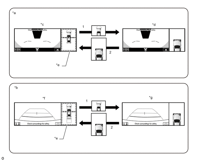
*a Panoramic view and wide front view screen displayed while shift position is not in P or R *b Panoramic view and rear view screen displayed *c Panoramic view and wide front view screen *d Panoramic view and wide front view screen (Front left view magnified) *e Panoramic view screen *f Panoramic view and rear view screen *g Panoramic view and rear view screen (Front left view magnified) - - Screen Transition Conditions No. Screen Transition Conditions (1) Any of the 2 areas on the panoramic view screen is selected while the vehicle speed is approximately 20 km/h (12 mph) or less and the Lexus parking assist-sensor system is turned on. (2) The remote touch switch is pressed on the panoramic view zoom screen, or either of the following conditions is met:
-
The vehicle speed changes from approximately 20 km/h (12 mph) or less to over approximately 20 km/h (12 mph).
-
The Lexus parking assist-sensor system is turned off.
-
-
-
When the outer rear view mirror assembly is retracted
-
When the outer rear view mirrors are retracted, the screen changes according to the current screen display, as follows.
Figure 4. Screen Transition
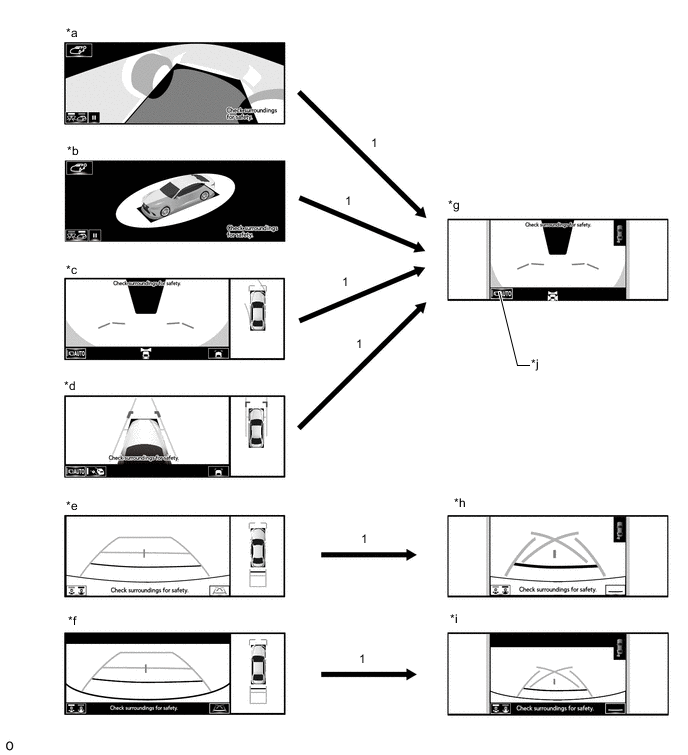
*a See through view screen *b Moving view screen *c Panoramic view and wide front view screen *d Panoramic view and side clearance view screen *e Panoramic view and rear view screen *f Panoramic view and wide rear view screen *g Two side view and wide front view screen *h Two side view and rear view screen *i Two side view and wide rear view screen *j Shift position in any position other than P Screen Transition Conditions No. Screen Transition Conditions (1) When outer rear view mirror assembly is retracted
-
-
-
OPERATION EXPLANATION
-
The reverse position signal is sent from the shift position switch to the parking assist ECU when the shift position is moved to R.
-
An appropriate steering angle and timing information can be provided for the driver. This is based on the information from the steering angle sensor signal and the vehicle angle data signal that are sent to the parking assist ECU.
Tech Tips
The steering angle sensor signal is used to control parking assist only for estimated guide line mode.
-
-
COMMUNICATION SYSTEM OUTLINE
-
CAN communication system
-
The panoramic view monitor system uses CAN communication for data communications between the parking assist ECU and each ECU.
-
If a problem occurs in the CAN communication line, the parking assist ECU outputs a CAN communication malfunction DTC. (To check, use the GTS.)
-
If a problem occurs in the CAN communication line, the parking assist ECU outputs a CAN communication malfunction DTC. (To check, use the multi-display diagnosis screen.)
-
If a CAN communication line malfunction DTC is output, repair the malfunction in the communication line and troubleshoot the panoramic view monitor system when data communication is normal.
-
Since the CAN communication line has its own length and route, it cannot be repaired temporarily with a bypass wire, etc.
-
-
-
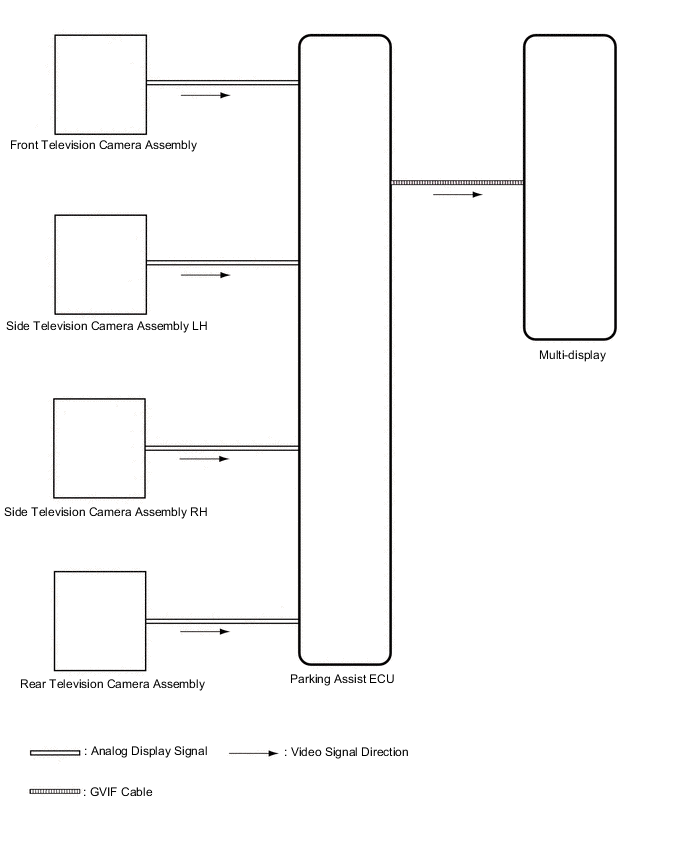
VIDEO SIGNALS
-
Video signal circuit
-
Video signals from the front television camera assembly are input into the parking assist ECU via analog communication lines (vehicle wire harness).
-
Video signals from the side television camera assembly LH are input into the parking assist ECU via analog communication lines (vehicle wire harness).
-
Video signals from the side television camera assembly RH are input into the parking assist ECU via analog communication lines (vehicle wire harness).
-
Video signals from the rear television camera assembly are input into the parking assist ECU via analog communication lines (vehicle wire harness).
-
Video signals from the parking assist ECU are input into the multi-display via GVIF cable.
-
-
Screen display
-
Video signals input from each camera are processed in the parking assist ECU and displayed on the multi-display as the panoramic view monitor system screen.
-
-
-
DIAGNOSTIC FUNCTION OUTLINE
-
This panoramic view monitor system has a diagnostic function displayed in the multi-display. This function enables the calibration (adjustment and verification) of the panoramic view monitor system.
-
The panoramic view monitor system can check the following items by using the GTS.
Item Proceed to DTC Data List / Active Test
-
-
CALIBRATION
-
Use the panoramic view monitor system diagnosis screen for calibration and checking of the panoramic view monitor system.
Note
Part replacement and work performed during servicing may require calibration of the panoramic view monitor system and other systems.
-