CYLINDER HEAD DISASSEMBLY

CAUTION / NOTICE / HINT
The necessary procedures (adjustment, calibration, initialization, or registration) that must be performed after parts are removed and installed, or replaced during engine unit removal/installation are shown below.
| Replaced Part or Performed Procedure | Necessary Procedure | Effect/Inoperative Function when Necessary Procedure not Performed | Link | |
|---|---|---|---|---|
| Battery terminal is disconnected/reconnected | Perform steering sensor zero point calibration | Lane departure alert system (w/ Steering Control) | ||
| Pre-collision system | ||||
| Memorize steering angle neutral point | Parking assist monitor system | |||
| Panoramic view monitor system | ||||
| Replacement of ECM | Vehicle Identification Number (VIN) registration | MIL comes on | ||
| Perform code registration (Immobiliser system) | Engine start function | See Service Bulletin for the registration method. | ||
|
Inspection after repair |
|
||
| Replacement of automatic transaxle assembly | Perform the following procedures in the order shown:
|
|
Click here for U761E Initialization Click here for U761E Registration |
|
| Replacement of ECM (If possible, read the transaxle compensation code from the previous ECM) |
Possible | Perform the following procedures in the order shown:
|
||
| Impossible | Perform the following procedures in the order shown:
|
|||
| Replacement of ECM | Perform code registration (Immobiliser function) |
|
See Service Bulletin for the registration method. | |
| Suspension, tires, etc.*1 | Rear television camera assembly optical axis (Back camera position setting) | Parking assist monitor system | Click here for Initialization Click here for Calibration |
|
|
Panoramic view monitor system | Click here for Initialization Click here for Calibration |
||
| Replacement of front bumper assembly | Front television camera view adjustment | |||
| Front wheel alignment adjustment | Perform system variant learning and acceleration sensor zero point calibration. |
|
||
PROCEDURE
-
REMOVE INTAKE VALVE
-
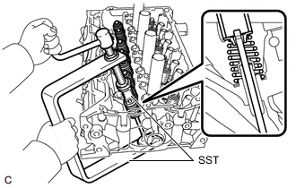
Using SST, compress each compression spring and remove the 8 valve spring retainer locks.
- SST
- 09202-70020
Tech Tips
Arrange the removed parts in such a way that they can be reinstalled to their original locations.
-
Remove the 8 valve spring retainers, 8 compression springs and 8 intake valves from the cylinder head sub-assembly.
Tech Tips
Arrange the removed parts in such a way that they can be reinstalled to their original locations.
-
-
REMOVE EXHAUST VALVE
-
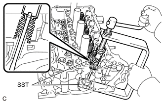
Using SST, compress the compression spring and remove the 2 valve spring retainer locks.
- SST
- 09202-70020
-
Remove the valve spring retainer, compression spring and exhaust valve from the cylinder head sub-assembly.
Tech Tips
Arrange the removed parts in the correct order.
-
-
REMOVE VALVE STEM OIL SEAL
-
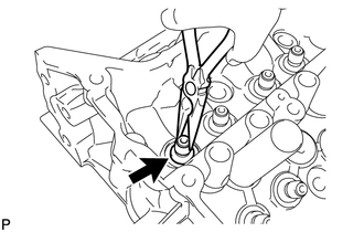
Using needle-nose pliers, remove the valve stem oil seals.
-
-
REMOVE EXHAUST VALVE SPRING SEAT
-
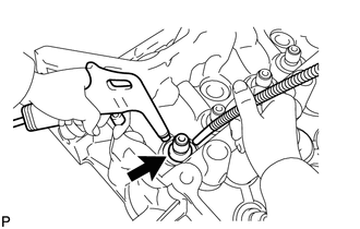
Using compressed air and a Magnet Hand, remove the valve spring seats by blowing air onto them.
-
-
REMOVE NO. 1 STRAIGHT SCREW PLUG
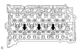
Note
If coolant leaks from a No. 1 straight screw plug or a plug is corroded, replace it.
-
Using a 10 mm hexagon wrench, remove the 3 No. 1 straight screw plugs and 3 gaskets.
-
-
REMOVE NO. 2 STRAIGHT SCREW PLUG
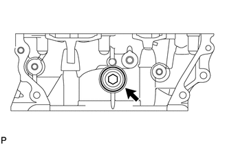
Note
If coolant leaks from the No. 2 straight screw plug or the plug is corroded, replace it.
-
Using a 14 mm hexagon wrench, remove the No. 2 straight screw plug and gasket.
-
-
REMOVE CYLINDER HEAD STUD BOLT
Note
If a cylinder head stud bolt is deformed or its threads are damaged, replace it.