DYNAMIC TORQUE CONTROL AWD SYSTEM, Diagnostic DTC:C1241/94

| DTC Code | DTC Name |
|---|---|
| C1241/94 | Low Power Supply Voltage |
DESCRIPTION
If a malfunction in the power source circuit occurs, or a malfunction in communication with the skid control ECU (brake actuator assembly) or in a speed sensor occurs, the 4WD ECU assembly will prohibit operations by the fail-safe function.
| DTC No. | Detection Item | DTC Detection Condition | Trouble Area |
|---|---|---|---|
| C1241/94 | Low Power Supply Voltage |
|
|
| Vehicle Condition | ||||
|---|---|---|---|---|
| Pattern 1 | Pattern 2 | Pattern 3 | ||
| Diagnosis Condition | - | - | - | - |
| Malfunction Status | At a vehicle speed of 3 km/h (2 mph) or more, voltage of IG1 terminal is 9.5 V or less. | ○ | - | - |
| With the IG1 terminal voltage 9.5 V or less, communication with the skid control ECU (brake actuator assembly) is impossible. | - | ○ | - | |
| With the IG1 terminal voltage 17 V or more, communication with the skid control ECU (brake actuator assembly) is impossible. | - | - | ○ | |
| Detection Time | 10 seconds or more | 60 seconds or more | 3 seconds or more | |
| Number of Trips | 1 trip | 1 trip | 1 trip | |
WIRING DIAGRAM
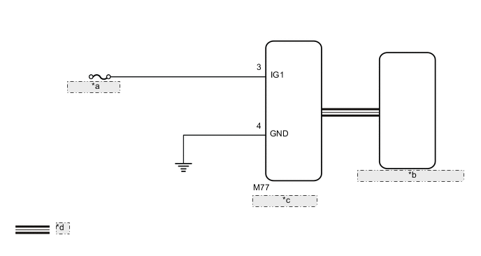
| *a | ECU-IG1 NO. 2 |
| *b | Skid Control ECU (Brake Actuator Assembly) |
| *c | 4WD ECU Assembly |
| *d | CAN Communication Line |
CAUTION / NOTICE / HINT
PROCEDURE
-
CHECK FOR DTC (CAN COMMUNICATION SYSTEM AND BRAKE CONTROL SYSTEM)
-
Check if CAN communication system DTCs are output.
-
Start the engine.
-
Drive the vehicle, accelerate to a speed of 3 km/h (2 mph) or more for 60 seconds or more, and check if the speed sensor DTC (brake control system DTC) is output.
Chassis > ABS/VSC/TRC/EPB > Trouble CodesResult Result Proceed to Neither CAN communication system DTC nor speed sensor DTC (brake control system DTC) is output A CAN communication system DTC is output B Speed sensor DTC (brake control system DTC) is output C
B 
GO TO CAN COMMUNICATION SYSTEM (HOW TO PROCEED WITH TROUBLESHOOTING) Click here
C
REPAIR CIRCUIT INDICATED BY OUTPUT CODE (BRAKE CONTROL SYSTEM) Click here
A 
-
-
INSPECT BATTERY
-
Check the battery voltage.
Standard voltage 11 to 14 V Result Proceed to OK NG
NG
CHECK CHARGING SYSTEM Click here
OK
-
-
CHECK HARNESS AND CONNECTOR (IG1 TERMINAL)
-
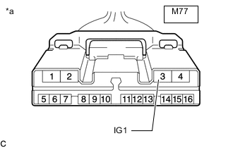
*a Front view of wire harness connector
(to 4WD ECU Assembly)
Disconnect the 4WD ECU assembly connector.
-
Turn the ignition switch to ON.
-
Measure the voltage according to the value(s) in the table below.
Standard Voltage Tester Connection Switch Condition Specified Condition M77-3 (IG1) - Body ground Ignition switch ON 11 to 14 V Result Proceed to OK NG
NG
REPAIR OR REPLACE HARNESS OR CONNECTOR
OK
-
-
CHECK HARNESS AND CONNECTOR (GND TERMINAL)
-
Turn the ignition switch off.
-
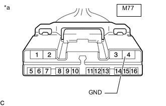
*a Front view of wire harness connector
(to 4WD ECU Assembly)
Measure the resistance according to the value(s) in the table below.
Standard Resistance Tester Connection Condition Specified Condition M77-4 (GND) - Body ground Always Below 1 Ω Result Proceed to OK NG
NG
REPAIR OR REPLACE HARNESS OR CONNECTOR
OK
-
-
RECONFIRM DTC
-
Clear the DTC.
Chassis > Four Wheel Drive > Clear DTCs -
Start the engine.
-
Drive the vehicle, accelerate to a speed of 3 km/h (2 mph) or more, and check if the same DTC is output.
Chassis > Four Wheel Drive > Trouble CodesResult Result Proceed to DTC is output A DTC is not output B Tech Tips
Reinstall the sensor, connectors, etc. and restore the vehicle to its prior condition before rechecking DTCs.
A
REPLACE 4WD ECU ASSEMBLY Click here
B
CHECK FOR INTERMITTENT PROBLEMS Click here
-