NAVIGATION SYSTEM, Diagnostic DTC:B1323, B1324, B1325, B1326
| DTC Code | DTC Name |
|---|---|
| B1323 | Lost Communication with Haptic Device |
| B1324 | Lost Communication with Meter |
| B1325 | Lost Communication with HUD |
| B1326 | Lost Communication with Clock Device (Local-CAN) |
DESCRIPTION
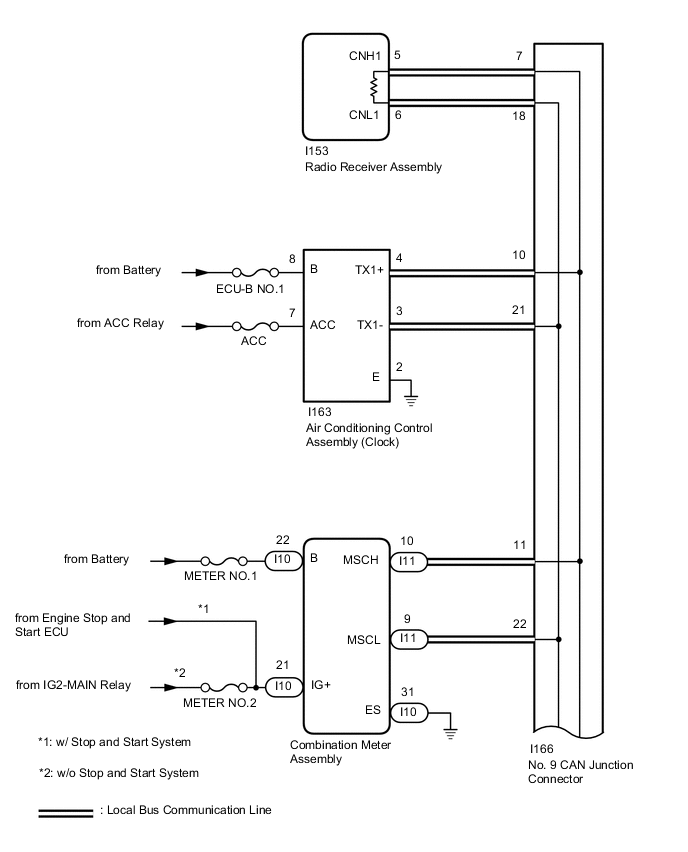
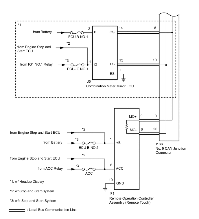
These DTCs are stored when communication between the radio receiver assembly and remote operation controller assembly (remote touch), combination meter assembly, combination meter mirror ECU* or air conditioning control assembly (clock) is not possible.
-
*: w/ Headup Display
| DTC No. | Detection Item | DTC Detection Condition | Trouble Area |
|---|---|---|---|
| B1323 | Lost Communication with Haptic Device | CAN reception error |
|
| B1324 | Lost Communication with Meter | CAN reception error |
|
| B1325 | Lost Communication with HUD | CAN reception error |
|
| B1326 | Lost Communication with Clock Device (Local-CAN) | CAN reception error |
|
Tech Tips
The radio receiver assembly is the master unit.
WIRING DIAGRAM
CAUTION / NOTICE / HINT
Note
-
When replacing the radio receiver assembly, always replace it with a new one.
If a radio receiver assembly which was installed to another vehicle is used, the following may occur:
-
A communication malfunction DTC may be stored.
-
The radio receiver assembly may not operate normally.
-
After turning the engine switch off, waiting time may be required before disconnecting the cable from the negative (-) battery terminal. Therefore, make sure to read the disconnecting the cable from the negative (-) battery terminal notices before proceeding with work.
-
Inspect the fuses for circuits related to this system before performing the following procedure.
Tech Tips
-
B1323, B1324, B1325 and B1326 will not continue to output when clear DTC is performed even if the malfunction continues.
-
Depending on the parts that are replaced during vehicle inspection or maintenance, performing initialization, registration or calibration may be needed. Refer to Precaution for Navigation System.
PROCEDURE
-
CHECK DTC
-
Check for DTCs.
Body Electrical > Navigation System > Trouble CodesResult *: w/ Headup DisplayResult Proceed to DTCs B1323, B1324, B1325* and B1326 are output A DTC B1323 is output B DTC B1324 is output C DTCs B1325 is output* D DTC B1326 is output E
B 
CHECK HARNESS AND CONNECTOR (REMOTE OPERATION CONTROLLER ASSEMBLY [REMOTE TOUCH] POWER SOURCE) Click here
C
CHECK HARNESS AND CONNECTOR (COMBINATION METER ASSEMBLY POWER SOURCE) Click here
D
CHECK HARNESS AND CONNECTOR (COMBINATION METER MIRROR ECU POWER SOURCE) Click here
E
CHECK HARNESS AND CONNECTOR (AIR CONDITIONING CONTROL ASSEMBLY [CLOCK] POWER SOURCE) Click here
A 
-
-
CHECK LOCAL BUS
-
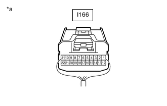
*a Rear view of wire harness connector
(No. 9 CAN Junction Connector)
Disconnect the cable from the negative (-) battery terminal.
-
Measure the resistance according to the value(s) in the table below.
Standard Resistance Tester Connection Condition Specified Condition I166-7 - I166-18 Cable disconnected from negative (-) battery terminal 54 to 69 Ω Result Result Proceed to OK A NG (Below 54 Ω) B NG (70 Ω or higher) C
A 
USE SIMULATION METHOD TO CHECK Click here
B
CHECK HARNESS AND CONNECTOR (NO. 9 CAN JUNCTION CONNECTOR - RADIO RECEIVER ASSEMBLY) Click here
C
CHECK HARNESS AND CONNECTOR (NO. 9 CAN JUNCTION CONNECTOR - RADIO RECEIVER ASSEMBLY) Click here
-
-
CHECK HARNESS AND CONNECTOR (REMOTE OPERATION CONTROLLER ASSEMBLY [REMOTE TOUCH] POWER SOURCE)
-
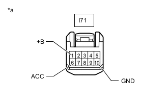
*a Front view of wire harness connector
(to Remote Operation Controller Assembly [Remote Touch])
Disconnect the remote operation controller assembly (remote touch) connector.
-
Measure the resistance according to the value(s) in the table below.
Standard Resistance Tester Connection Condition Specified Condition I71-10 (GND) - Body ground Always Below 1 Ω -
Measure the voltage according to the value(s) in the table below.
Standard Voltage *1: w/o Stop and Start SystemTester Connection Condition Specified Condition I71-1 (+B) - Body ground Always 11 to 14 V*1
10.5 to 16 V*2
I71-6 (ACC) - Body ground Engine switch on (ACC) 11 to 14 V*1
10.5 to 16 V*2
*2: w/ Stop and Start System
Result Proceed to OK NG
NG
REPAIR OR REPLACE HARNESS OR CONNECTOR
OK
-
-
CHECK HARNESS AND CONNECTOR (REMOTE OPERATION CONTROLLER ASSEMBLY [REMOTE TOUCH] - NO. 9 CAN JUNCTION CONNECTOR)
-
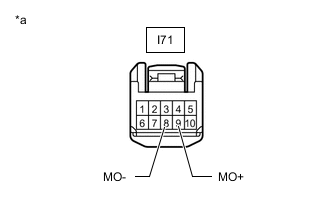
*a Front view of wire harness connector
(to Remote Operation Controller Assembly [Remote Touch])
Disconnect the cable from the negative (-) battery terminal.
-
Disconnect the remote operation controller assembly (remote touch) connector.
-
Measure the resistance according to the value(s) in the table below.
Standard Resistance Tester Connection Condition Specified Condition I71-9 (MO+) - I71-8 (MO-) Cable disconnected from negative (-) battery terminal 108 to 132 Ω Result Proceed to OK NG
OK
REPLACE REMOTE OPERATION CONTROLLER ASSEMBLY Click here
NG
REPAIR OR REPLACE HARNESS OR CONNECTOR
-
-
CHECK HARNESS AND CONNECTOR (NO. 9 CAN JUNCTION CONNECTOR - RADIO RECEIVER ASSEMBLY)
-
Disconnect the No. 9 CAN junction connector.
-

*a Rear view of wire harness connector
(No. 9 CAN Junction Connector)
Measure the resistance according to the value(s) in the table below.
Standard Resistance Tester Connection Condition Specified Condition I166-7 - I166-18 Cable disconnected from negative (-) battery terminal 108 to 132 Ω Result Proceed to OK NG
NG
CHECK HARNESS AND CONNECTOR (RADIO RECEIVER ASSEMBLY - NO. 9 CAN JUNCTION CONNECTOR) Click here
OK
-
-
CHECK HARNESS AND CONNECTOR (NO. 9 CAN JUNCTION CONNECTOR - REMOTE OPERATION CONTROLLER ASSEMBLY [REMOTE TOUCH])
-

*a Rear view of wire harness connector
(No. 9 CAN Junction Connector)
Disconnect the No. 9 CAN junction connector.
-
Measure the resistance according to the value(s) in the table below.
Standard Resistance Tester Connection Condition Specified Condition I166-9 - I166-20 Cable disconnected from negative (-) battery terminal 108 to 132 Ω Result Proceed to OK NG
NG
CHECK HARNESS AND CONNECTOR (REMOTE OPERATION CONTROLLER ASSEMBLY [REMOTE TOUCH] - NO. 9 CAN JUNCTION CONNECTOR) Click here
OK
-
-
CHECK HARNESS AND CONNECTOR (NO. 9 CAN JUNCTION CONNECTOR - COMBINATION METER ASSEMBLY)
-
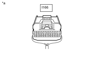
*a Rear view of wire harness connector
(No. 9 CAN Junction Connector)
Disconnect the No. 9 CAN junction connector.
-
Measure the resistance according to the value(s) in the table below.
Standard Resistance Tester Connection Condition Specified Condition I166-11 - I166-22 Cable disconnected from negative (-) battery terminal 200 Ω or higher Result Proceed to OK NG
NG
CHECK HARNESS AND CONNECTOR (COMBINATION METER ASSEMBLY - NO. 9 CAN JUNCTION CONNECTOR) Click here
OK
-
-
CHECK VEHICLE TYPE
-
Check the vehicle type.
Result Result Proceed to w/ Headup Display A w/o Headup Display B
B
GO TO STEP 10 Click here
A
-
-
CHECK HARNESS AND CONNECTOR (NO. 9 CAN JUNCTION CONNECTOR - COMBINATION METER MIRROR ECU)
-
Disconnect the No. 9 CAN junction connector.
-
*a Rear view of wire harness connector
(No. 9 CAN Junction Connector)
Measure the resistance according to the value(s) in the table below.
Standard Resistance Tester Connection Condition Specified Condition I166-8 - I166-19 Cable disconnected from negative (-) battery terminal 200 Ω or higher Result Proceed to OK NG
NG
CHECK HARNESS AND CONNECTOR (COMBINATION METER MIRROR ECU - NO. 9 CAN JUNCTION CONNECTOR) Click here
OK
-
-
CHECK HARNESS AND CONNECTOR (NO. 9 CAN JUNCTION CONNECTOR - AIR CONDITIONING CONTROL ASSEMBLY [CLOCK])
-
*a Rear view of wire harness connector
(No. 9 CAN Junction Connector)
Disconnect the No. 9 CAN junction connector.
-
Measure the resistance according to the value(s) in the table below.
Standard Resistance Tester Connection Condition Specified Condition I166-10 - I166-21 Cable disconnected from negative (-) battery terminal 200 Ω or higher Result Proceed to OK NG
OK
REPLACE NO. 9 CAN JUNCTION CONNECTOR
NG
CHECK HARNESS AND CONNECTOR (AIR CONDITIONING CONTROL ASSEMBLY (CLOCK) - NO. 9 CAN JUNCTION CONNECTOR) Click here
-
-
CHECK HARNESS AND CONNECTOR (RADIO RECEIVER ASSEMBLY - NO. 9 CAN JUNCTION CONNECTOR)
-
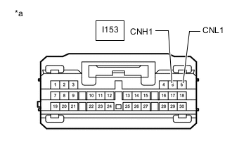
*a Front view of wire harness connector
(to Radio Receiver Assembly)
Disconnect the radio receiver assembly connector.
-
Measure the resistance according to the value(s) in the table below.
Standard Resistance Tester Connection Condition Specified Condition I153-5 (CNH1) - I153-6 (CNL1) Cable disconnected from negative (-) battery terminal 108 to 132 Ω Result Proceed to OK NG
OK
REPLACE RADIO RECEIVER ASSEMBLY Click here
NG
REPAIR OR REPLACE HARNESS OR CONNECTOR
-
-
CHECK HARNESS AND CONNECTOR (REMOTE OPERATION CONTROLLER ASSEMBLY [REMOTE TOUCH] - NO. 9 CAN JUNCTION CONNECTOR)
-

*a Front view of wire harness connector
(to Remote Operation Controller Assembly [Remote Touch])
Disconnect the remote operation controller assembly (remote touch) connector.
-
Measure the resistance according to the value(s) in the table below.
Standard Resistance Tester Connection Condition Specified Condition I71-9 (MO+) - I71-8 (MO-) Cable disconnected from negative (-) battery terminal 108 to 132 Ω Result Proceed to OK NG
OK
REPLACE REMOTE OPERATION CONTROLLER ASSEMBLY (REMOTE TOUCH) Click here
NG
REPAIR OR REPLACE HARNESS OR CONNECTOR
-
-
CHECK HARNESS AND CONNECTOR (COMBINATION METER ASSEMBLY - NO. 9 CAN JUNCTION CONNECTOR)
-
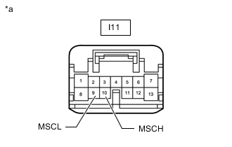
*a Front view of wire harness connector
(to Combination Meter Assembly)
Disconnect the combination meter assembly connector.
-
Measure the resistance according to the value(s) in the table below.
Standard Resistance Tester Connection Condition Specified Condition I11-10 (MSCH) - I11-9 (MSCL) Cable disconnected from negative (-) battery terminal 54 to 69 Ω Result Proceed to OK NG
OK
REPLACE COMBINATION METER ASSEMBLY Click here
NG
REPAIR OR REPLACE HARNESS OR CONNECTOR
-
-
CHECK HARNESS AND CONNECTOR (COMBINATION METER MIRROR ECU - NO. 9 CAN JUNCTION CONNECTOR)
-
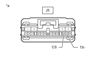
*a Front view of wire harness connector
(to Combination Meter Mirror ECU)
Disconnect the combination meter mirror ECU connector.
-
Measure the resistance according to the value(s) in the table below.
Standard Resistance Tester Connection Condition Specified Condition J5-14 (CS) - J5-15 (TX-) Cable disconnected from negative (-) battery terminal 54 to 69 Ω Result Proceed to OK NG
OK
REPLACE COMBINATION METER MIRROR ECU Click here
NG
REPAIR OR REPLACE HARNESS OR CONNECTOR
-
-
CHECK HARNESS AND CONNECTOR (AIR CONDITIONING CONTROL ASSEMBLY (CLOCK) - NO. 9 CAN JUNCTION CONNECTOR)
-

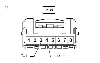
*a Front view of wire harness connector
(to Air Conditioning Control Assembly [Clock])
Disconnect the air conditioning control assembly (clock) connector.
-
Measure the resistance according to the value(s) in the table below.
Standard Resistance Tester Connection Condition Specified Condition I163-4 (TX1+) - I163-3 (TX1-) Cable disconnected from negative (-) battery terminal 54 to 69 Ω Result Proceed to OK NG
OK
REPLACE AIR CONDITIONING CONTROL ASSEMBLY (CLOCK) Click here
NG
REPAIR OR REPLACE HARNESS OR CONNECTOR
-
-
CHECK HARNESS AND CONNECTOR (COMBINATION METER ASSEMBLY POWER SOURCE)
-
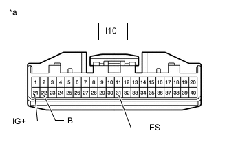
*a Front view of wire harness connector
(to Combination Meter Assembly)
Disconnect the combination meter assembly connector.
-
Measure the resistance according to the value(s) in the table below.
Standard Resistance Tester Connection Condition Specified Condition I10-31 (ES) - Body ground Always Below 1 Ω -
Measure the voltage according to the value(s) in the table below.
Standard Voltage *1: w/o Stop and Start SystemTester Connection Condition Specified Condition I10-22 (B) - Body ground Always 11 to 14 V I10-21 (IG+) - Body ground Engine switch on (IG) 11 to 14 V*1
10.5 to 16 V*2
*2: w/ Stop and Start System
Result Proceed to OK NG
NG
REPAIR OR REPLACE HARNESS OR CONNECTOR
OK
-
-
CHECK HARNESS AND CONNECTOR (COMBINATION METER ASSEMBLY - NO. 9 CAN JUNCTION CONNECTOR)
-

*a Front view of wire harness connector
(to Combination Meter Assembly)
Disconnect the cable from the negative (-) battery terminal.
-
Disconnect the combination meter assembly connector.
-
Measure the resistance according to the value(s) in the table below.
Standard Resistance Tester Connection Condition Specified Condition I11-10 (MSCH) - I11-9 (MSCL) Cable disconnected from negative (-) battery terminal 54 to 69 Ω Result Proceed to OK NG
OK
REPLACE COMBINATION METER ASSEMBLY Click here
NG
REPAIR OR REPLACE HARNESS OR CONNECTOR
-
-
CHECK HARNESS AND CONNECTOR (NO. 9 CAN JUNCTION CONNECTOR - RADIO RECEIVER ASSEMBLY)
-
Disconnect the cable from the negative (-) battery terminal.
-
Disconnect the No. 9 CAN junction connector.
-
*a Rear view of wire harness connector
(No. 9 CAN Junction Connector)
Measure the resistance according to the value(s) in the table below.
Standard Resistance Tester Connection Condition Specified Condition I166-7 - I166-18 Cable disconnected from negative (-) battery terminal 108 to 132 Ω Result Proceed to OK NG
NG
CHECK HARNESS AND CONNECTOR (RADIO RECEIVER ASSEMBLY - NO. 9 CAN JUNCTION CONNECTOR) Click here
OK
-
-
CHECK HARNESS AND CONNECTOR (NO. 9 CAN JUNCTION CONNECTOR - REMOTE OPERATION CONTROLLER ASSEMBLY [REMOTE TOUCH])
-
Disconnect the cable from the negative (-) battery terminal.
-
Disconnect the No. 9 CAN junction connector.
-
*a Rear view of wire harness connector
(No. 9 CAN Junction Connector)
Measure the resistance according to the value(s) in the table below.
Standard Resistance Tester Connection Condition Specified Condition I166-9 - I166-20 Cable disconnected from negative (-) battery terminal 108 to 132 Ω Result Proceed to OK NG
OK
REPLACE NO. 9 CAN JUNCTION CONNECTOR
NG
CHECK HARNESS AND CONNECTOR (REMOTE OPERATION CONTROLLER ASSEMBLY [REMOTE TOUCH] - NO. 9 CAN JUNCTION CONNECTOR) Click here
-
-
CHECK HARNESS AND CONNECTOR (COMBINATION METER MIRROR ECU POWER SOURCE)
-
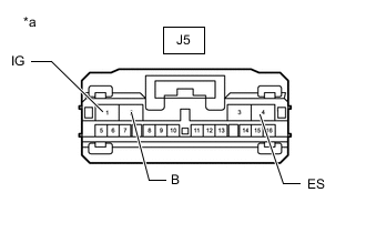
*a Front view of wire harness connector
(to Combination Meter Mirror ECU)
Disconnect the combination meter mirror ECU connector.
-
Measure the resistance according to the value(s) in the table below.
Standard Resistance Tester Connection Condition Specified Condition J5-4 (ES) - Body ground Always Below 1 Ω -
Measure the voltage according to the value(s) in the table below.
Standard Voltage *1: w/o Stop and Start SystemTester Connection Condition Specified Condition J5-2 (B) - Body ground Always 11 to 14 V J5-1 (IG) - Body ground Engine switch on (IG) 11 to 14 V*1
10.5 to 16 V*2
*2: w/ Stop and Start System
Result Proceed to OK NG
NG
REPAIR OR REPLACE HARNESS OR CONNECTOR
OK
-
-
CHECK HARNESS AND CONNECTOR (COMBINATION METER MIRROR ECU - NO. 9 CAN JUNCTION CONNECTOR)
-
*a Front view of wire harness connector
(to Combination Meter Mirror ECU)
Disconnect the cable from the negative (-) battery terminal.
-
Disconnect the combination meter mirror ECU connector.
-
Measure the resistance according to the value(s) in the table below.
Standard Resistance Tester Connection Condition Specified Condition J5-14 (CS) - J5-15 (TX-) Cable disconnected from negative (-) battery terminal 54 to 69 Ω Result Proceed to OK NG
OK
REPLACE COMBINATION METER MIRROR ECU Click here
NG
REPAIR OR REPLACE HARNESS OR CONNECTOR
-
-
CHECK HARNESS AND CONNECTOR (RADIO RECEIVER ASSEMBLY - NO. 9 CAN JUNCTION CONNECTOR)
-
*a Front view of wire harness connector
(to Radio Receiver Assembly)
Disconnect the radio receiver assembly connector.
-
Measure the resistance according to the value(s) in the table below.
Standard Resistance Tester Connection Condition Specified Condition I153-5 (CNH1) - I153-6 (CNL1) Cable disconnected from negative (-) battery terminal 108 to 132 Ω Result Proceed to OK NG
OK
REPLACE RADIO RECEIVER ASSEMBLY Click here
NG
REPAIR OR REPLACE HARNESS OR CONNECTOR
-
-
CHECK HARNESS AND CONNECTOR (REMOTE OPERATION CONTROLLER ASSEMBLY [REMOTE TOUCH] - NO. 9 CAN JUNCTION CONNECTOR)
-
*a Front view of wire harness connector
(to Remote Operation Controller Assembly [Remote Touch])
Disconnect the remote operation controller assembly (remote touch) connector.
-
Measure the resistance according to the value(s) in the table below.
Standard Resistance Tester Connection Condition Specified Condition I71-9 (MO+) - I71-8 (MO-) Cable disconnected from negative (-) battery terminal 108 to 132 Ω Result Proceed to OK NG
OK
REPLACE REMOTE OPERATION CONTROLLER ASSEMBLY (REMOTE TOUCH) Click here
NG
REPAIR OR REPLACE HARNESS OR CONNECTOR
-
-
CHECK HARNESS AND CONNECTOR (AIR CONDITIONING CONTROL ASSEMBLY [CLOCK] POWER SOURCE)
-
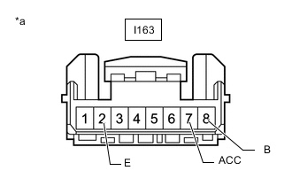
*a Front view of wire harness connector
(to Air Conditioning Control Assembly [Clock])
Disconnect the air conditioning control assembly (clock) connector.
-
Measure the resistance according to the value(s) in the table below.
Standard Resistance Tester Connection Condition Specified Condition I163-2 (E) - Body ground Always Below 1 Ω -
Measure the voltage according to the value(s) in the table below.
Standard Voltage Tester Connection Condition Specified Condition I163-8 (B) - Body ground Always 11 to 14 V I163-7 (ACC) - Body ground Engine switch on (ACC) 11 to 14 V Result Proceed to OK NG
NG
REPAIR OR REPLACE HARNESS OR CONNECTOR
OK
-
-
CHECK HARNESS AND CONNECTOR (AIR CONDITIONING CONTROL ASSEMBLY [CLOCK] - NO. 9 CAN JUNCTION CONNECTOR)
-
*a Front view of wire harness connector
(to Air Conditioning Control Assembly [Clock])
Disconnect the cable from the negative (-) battery terminal.
-
Disconnect the air conditioning control assembly (clock) connector.
-
Measure the resistance according to the value(s) in the table below.
Standard Resistance Tester Connection Condition Specified Condition I163-4 (TX1+) - I163-3 (TX1-) Cable disconnected from negative (-) battery terminal 54 to 69 Ω Result Proceed to OK NG
OK
REPLACE AIR CONDITIONING CONTROL ASSEMBLY (CLOCK) Click here
NG
REPAIR OR REPLACE HARNESS OR CONNECTOR
-