ELECTRONICALLY CONTROLLED BRAKE SYSTEM(w/o Vacuum Brake Booster), Diagnostic DTC:C1247, C1392
| DTC Code | DTC Name |
|---|---|
| C1247 | Stroke Sensor |
| C1392 | Zero Point Calibration of Stroke Sensor undone |
DESCRIPTION
The brake pedal stroke sensor assembly sends a signal about the pedal stroke to the skid control ECU assembly.
| DTC No. | Detection Item | INF Code | DTC Detection Condition | Trouble Area | Note |
|---|---|---|---|---|---|
| C1247 | Stroke Sensor | 171 172 173 174 175 181 182 183 |
|
|
- |
| C1392 | Zero Point Calibration of Stroke Sensor undone | - | Zero point calibration of brake pedal stroke sensor assembly is unfinished. | Brake pedal stroke sensor zero point calibration incomplete (Initialization and calibration of linear solenoid valve incomplete) | - |
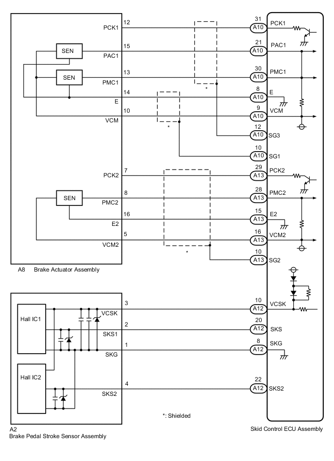
WIRING DIAGRAM
CAUTION / NOTICE / HINT
Note
When replacing the skid control ECU assembly, brake actuator assembly or brake pedal stroke sensor assembly, perform initialization and calibration of the linear solenoid valve.
PROCEDURE
-
CHECK BRAKE PEDAL
-
Check that the brake pedal and the brake pedal stroke sensor assembly are properly installed and that the pedal can be depressed normally.
-
Check and adjust the brake pedal height.
-
Adjust the brake pedal stroke sensor assembly.
Result Proceed to NEXT
NEXT 
-
-
CHECK HARNESS AND CONNECTOR (SKID CONTROL ECU ASSEMBLY - BRAKE PEDAL STROKE SENSOR ASSEMBLY)
-
Make sure that there is no looseness at the locking part and the connecting part of the connectors.
-
Disconnect the A12 skid control ECU assembly connector.
-
Disconnect the A2 brake pedal stroke sensor assembly connector.
-
Check both the connector case and the terminal for deformation and corrosion.
OK No deformation or corrosion. -
Measure the resistance according to the value(s) in the table below.
Standard Resistance Tester Connection Condition Specified Condition A12-8 (SKG) - A2-1 (SKG) Always Below 1 Ω A12-8 (SKG) or A2-1 (SKG) - Body ground Always 10 kΩ or higher A12-10 (VCSK) - A2-3 (VCSK) Always Below 1 Ω A12-10 (VCSK) or A2-3 (VCSK) - Body ground Always 10 kΩ or higher A12-20 (SKS) - A2-2 (SKS1) Always Below 1 Ω A12-20 (SKS) or A2-2 (SKS1) - Body ground Always 10 kΩ or higher A12-22 (SKS2) - A2-4 (SKS2) Always Below 1 Ω A12-22 (SKS2) or A2-4 (SKS2) - Body ground Always 10 kΩ or higher Result Proceed to OK NG
NG 
REPAIR OR REPLACE HARNESS OR CONNECTOR
OK
-
-
PERFORM INITIALIZATION AND CALIBRATION OF LINEAR SOLENOID VALVE
-
Reconnect the A12 skid control ECU assembly connector.
-
Reconnect the A2 brake pedal stroke sensor assembly connector.
-
Perform initialization and calibration of the linear solenoid valve.
Chassis > ABS/VSC/TRC > UtilityTester Display ECB Utility ECB: Electronically Controlled Brake System
Result Proceed to NEXT
NEXT
-
-
RECONFIRM DTC
-
Turn the engine switch off.
-
Clear the DTCs.
Chassis > ABS/VSC/TRC > Clear DTCs -
Turn the engine switch off.
-
Start the engine.
-
Perform a road test.
-
Check if the same DTC is output.
Chassis > ABS/VSC/TRC > Trouble CodesResult Result Proceed to DTCs C1247 and/or C1392 are output. A DTCs C1247 and C1392 are not output. B
B
END
A
-
-
INSPECT SKID CONTROL ECU ASSEMBLY (SENSOR POWER SUPPLY OUTPUT)
-
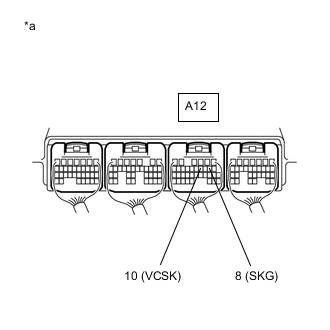
*a Component with harness connected
(Skid Control ECU Assembly)
Turn the engine switch on (IG).
-
Measure the voltage according to the value(s) in the table below.
Standard Voltage Tester Connection Switch Condition Specified Condition A12-10 (VCSK) - Body ground Engine switch on (IG) 4.5 to 5.5 V -
Turn the engine switch off.
-
Measure the resistance according to the value(s) in the table below.
Standard Resistance Tester Connection Switch Condition Specified Condition A12-8 (SKG) - Body ground Engine switch off Below 1 Ω Result Proceed to OK NG
NG
REPLACE SKID CONTROL ECU ASSEMBLY Click here
OK
-
-
READ VALUE USING GTS (BRAKE PEDAL STROKE SENSOR ASSEMBLY)
-
Mount a pedal effort gauge.
-
Connect the GTS to the DLC3.
-
Turn the engine switch on (IG).
-
Select the Data List on the GTS.
Chassis > ABS/VSC/TRC > Data ListTester Display Measurement Item Range Normal Condition Diagnostic Note Stroke Sensor Brake pedal stroke sensor assembly 1 Min.: 0.00 V, Max.: 5.00 V Brake pedal released: 0.80 to 1.20 V Reading increases when brake pedal is depressed Stroke Sensor2 Brake pedal stroke sensor assembly 2 Min.: 0.00 V, Max.: 5.00 V Brake pedal released: 3.80 to 4.20 V Reading decreases when brake pedal is depressed
Chassis > ABS/VSC/TRC > Data ListTester Display Stroke Sensor Stroke Sensor2 -
When depressing the brake pedal with the amount of force listed in the table below, check that the output value displayed on the GTS is within the standard voltage.
Tech Tips
The brake pedal must be depressed gradually.
Standard Voltage Brake Effort
N (kgf, lbf)
Stroke Sensor
(Tester Display)
Stroke Sensor2
(Tester Display)
50 (5, 11.2) 1.39 to 1.79 V 3.18 to 3.58 V 100 (10, 22.5) 1.61 to 2.01 V 2.96 to 3.36 V 150 (15, 33.7) 1.77 to 2.17 V 2.80 to 3.20 V 200 (20, 45.0) 1.86 to 2.26 V 2.71 to 3.11 V Result Proceed to OK NG
NG
REPLACE BRAKE PEDAL STROKE SENSOR ASSEMBLY Click here
OK
-
-
CHECK HARNESS AND CONNECTOR (SKID CONTROL ECU ASSEMBLY - BRAKE ACTUATOR ASSEMBLY)
-
Turn the engine switch off.
-
Make sure that there is no looseness at the locking part and the connecting part of the connectors.
-
Disconnect the A13 and A10 skid control ECU assembly connectors.
-
Disconnect the A8 brake actuator assembly connector.
-
Measure the resistance according to the value(s) in the table below.
Standard Resistance Tester Connection Condition Specified Condition A10-9 (VCM) - A8-10 (VCM) Always Below 1 Ω A10-9 (VCM) or A8-10 (VCM) - Body ground Always 10 kΩ or higher A10-21 (PAC1) - A8-15 (PAC1) Always Below 1 Ω A10-21 (PAC1) or A8-15 (PAC1) - Body ground Always 10 kΩ or higher A10-30 (PMC1) - A8-13 (PMC1) Always Below 1 Ω A10-30 (PMC1) or A8-13 (PMC1) - Body ground Always 10 kΩ or higher A10-8 (E) - A8-14 (E) Always Below 1 Ω A10-8 (E) or A8-14 (E) - Body ground Always 10 kΩ or higher A10-31 (PCK1) - A8-12 (PCK1) Always Below 1 Ω A10-31 (PCK1) or A8-12 (PCK1) - Body ground Always 10 kΩ or higher A13-16 (VCM2) - A8-5 (VCM2) Always Below 1 Ω A13-16 (VCM2) or A8-5 (VCM2) - Body ground Always 10 kΩ or higher A13-28 (PMC2) - A8-8 (PMC2) Always Below 1 Ω A13-28 (PMC2) or A8-8 (PMC2) - Body ground Always 10 kΩ or higher A13-15 (E2) - A8-16 (E2) Always Below 1 Ω A13-15 (E2) or A8-16 (E2) - Body ground Always 10 kΩ or higher A13-29 (PCK2) - A8-7 (PCK2) Always Below 1 Ω A13-29 (PCK2) or A8-7 (PCK2) - Body ground Always 10 kΩ or higher Result Proceed to OK NG
NG
REPAIR OR REPLACE HARNESS OR CONNECTOR
OK
-
-
INSPECT SKID CONTROL ECU ASSEMBLY (SENSOR POWER SUPPLY OUTPUT)
-
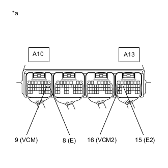
*a Component with harness connected
(Skid Control ECU Assembly)
Reconnect the A13 and A10 skid control ECU assembly connectors.
-
Reconnect the A8 brake actuator assembly connector.
-
Turn the engine switch on (IG).
-
Measure the voltage according to the value(s) in the table below.
Standard Voltage Tester Connection Switch Condition Specified Condition A10-9 (VCM) - Body ground Engine switch on (IG) 4.75 to 5.25 V A13-16 (VCM2) - Body ground Engine switch on (IG) 4.75 to 5.25 V -
Turn the engine switch off.
-
Measure the resistance according to the value(s) in the table below.
Standard Resistance Tester Connection Switch Condition Specified Condition A10-8 (E) - Body ground Engine switch off Below 1 Ω A13-15 (E2) - Body ground Engine switch off Below 1 Ω Result Proceed to OK NG
NG
REPLACE SKID CONTROL ECU ASSEMBLY Click here
OK
-
-
READ VALUE USING GTS (MASTER CYLINDER PRESSURE SENSOR)
-
Mount a pedal effort gauge.
-
Connect the GTS to the DLC3.
-
Turn the engine switch on (IG).
-
Select the Data List on the GTS.
Chassis > ABS/VSC/TRC > Data ListTester Display Measurement Item Range Normal Condition Diagnostic Note Master Cylinder Sensor Master cylinder pressure sensor 1 Min.: 0.00 V, Max.: 5.00 V Brake pedal released: 0.30 to 0.70 V Reading increases when brake pedal is depressed Master Cylinder Sensor2 Master cylinder pressure sensor 2 Min.: 0.00 V, Max.: 5.00 V Brake pedal released: 0.30 to 0.70 V Reading increases when brake pedal is depressed ECB Solenoid (SMC1) Master cut solenoid (SMC1) ON or OFF ON: Solenoid on
OFF: Solenoid off
ECB: Electronically Controlled Brake System ECB Solenoid (SMC2) Master cut solenoid (SMC2) ON or OFF ON: Solenoid on
OFF: Solenoid off
ECB: Electronically Controlled Brake System
Chassis > ABS/VSC/TRC > Data ListTester Display Master Cylinder Sensor Master Cylinder Sensor2 ECB Solenoid (SMC1) ECB Solenoid (SMC2) ECB: Electronically Controlled Brake System
-
Check the output value of the master cylinder pressure sensor as the brake pedal is depressed.
OK Output voltage is proportional to pedal stroke, and there is not a large difference in output between sensor 1 and sensor 2. Tech Tips
-
If DTCs are stored due to the brake pedal being depressed, and electronically controlled brake system control is prohibited, check the Freeze Frame Data recorded at the time the DTCs were stored.
-
If the Freeze Frame Data shows that there are no abnormalities in the output of the master cylinder pressure sensors and difference in the output between sensor 1 and sensor 2, proceed to the next step.
Result Proceed to OK NG -
OK
REPLACE SKID CONTROL ECU ASSEMBLY Click here
NG
REPLACE BRAKE ACTUATOR ASSEMBLY Click here
-