SFI SYSTEM(for Rear Heated Oxygen Sensor), Diagnostic DTC:P052012, P052014, P052024, P05202A, P052400
| DTC Code | DTC Name |
|---|---|
| P052012 | Engine Oil Pressure Sensor/Switch "A" Circuit Short to Battery |
| P052014 | Engine Oil Pressure Sensor/Switch "A" Circuit Short to Ground or Open |
| P052024 | Engine Oil Pressure Sensor/Switch "A" Signal Stuck High |
| P05202A | Engine Oil Pressure Sensor/Switch "A" Signal Stuck in Range |
| P052400 | Engine Oil Pressure Too Low |
DESCRIPTION
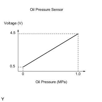
The oil pump is a variable discharge type. The oil pump maintains the oil pressure in the required for VVT operation at low engine speeds and for lubrication at high engine speeds, and reduces friction to lower excess oil pressure at middle engine speeds. The oil pressure sender gauge assembly detects the engine oil pressure.
| DTC No. | Detection Item | DTC Detection Condition | Trouble Area | MIL | Memory | Note |
|---|---|---|---|---|---|---|
| P052012 | Engine Oil Pressure Sensor/Switch "A" Circuit Short to Battery | The oil pressure sender gauge assembly output voltage is higher than 4.78 V for 5 seconds or more (1 trip detection logic). |
|
Comes on | DTC stored | SAE Code: P0523 |
| P052014 | Engine Oil Pressure Sensor/Switch "A" Circuit Short to Ground or Open | The oil pressure sender gauge assembly output voltage is less than 0.23 V for 5 seconds or more (1 trip detection logic). |
|
Comes on | DTC stored | SAE Code: P0522 |
| P052024 | Engine Oil Pressure Sensor/Switch "A" Signal Stuck High | The oil pressure sender gauge assembly output voltage is higher than the threshold value (1 trip detection logic). |
|
Comes on | DTC stored | SAE Code: P0521 |
| P05202A | Engine Oil Pressure Sensor/Switch "A" Signal Stuck in Range | The oil pressure sender gauge assembly output voltage is the same value for a certain period of time (1 trip detection logic). |
|
Comes on | DTC stored | SAE Code: P0521 |
| P052400 | Engine Oil Pressure Too Low | The oil pressure sender gauge assembly output voltage is at or below the threshold value (1 trip detection logic). |
|
Comes on | DTC stored | SAE Code: P0524 |
MONITOR DESCRIPTION
The ECM calculates the engine oil pressure based on the output voltage of the oil pressure sender gauge assembly. If any of the following are detected, the ECM will illuminate the MIL and store a DTC.
-
The output voltage of the oil pressure sender gauge assembly is outside of the specified range.
-
The actual output voltage of the oil pressure sender gauge assembly is different than the estimated output voltage based on the engine speed.
-
The oil pressure sender gauge assembly output voltage does not change for a certain period of time.
MONITOR STRATEGY
| Frequency of Operation | Continuous |
CONFIRMATION DRIVING PATTERN
-
Connect the GTS to the DLC3.
-
Turn the engine switch on (IG) and turn the GTS on.
-
Clear the DTCs (even if no DTCs are stored, perform the clear DTC procedure).
-
Turn the engine switch off and wait for at least 30 seconds.
-
Turn the engine switch on (IG) and turn the GTS on.
-
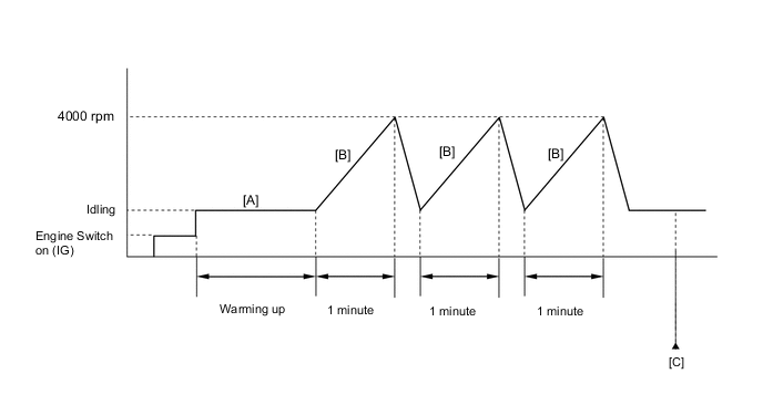
Start the engine and warm it up until the engine coolant temperature is 75°C (167°F) or higher with all the accessories switches turned off [A].
-
When the vehicle is stationery, gently depress the accelerator pedal until the engine speed increases to 4000 rpm for 1 minute, then release the accelerator pedal to return to the idling speed [B].
-
Repeat step [B] 3 times or more.
-
Enter the following menus: Powertrain / Engine / Trouble Codes [C].
-
Read the pending DTCs.
Tech Tips
-
If a pending DTC is output, the system is malfunctioning.
-
If a pending DTC is not output, perform the following procedure.
-
-
Enter the following menus: Powertrain / Engine / Utility / All Readiness.
-
Input the DTC: P052012, P052014, P052024, P05202A or P052400.
-
Check the DTC judgment result.
GTS Display Description NORMAL
-
DTC judgment completed
-
System normal
ABNORMAL
-
DTC judgment completed
-
System abnormal
INCOMPLETE
-
DTC judgment not completed
-
Perform driving pattern after confirming DTC enabling conditions
N/A
-
Unable to perform DTC judgment
-
Number of DTCs which do not fulfill DTC preconditions has reached ECU memory limit
Tech Tips
-
If the judgment result shows NORMAL, the system is normal.
-
If the judgment result shows ABNORMAL, the system has a malfunction.
-
If the judgment result shows INCOMPLETE or N/A, perform the Confirmation Driving Pattern and check the DTC judgment result again.
-
WIRING DIAGRAM
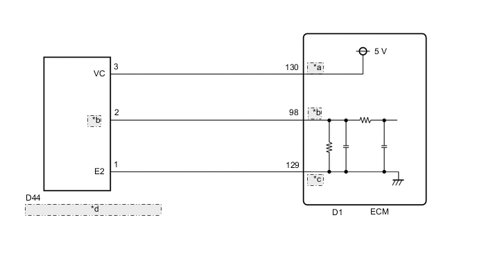
| *a | VCPE |
| *b | PEO |
| *c | EPEO |
| *d | Oil Pressure Sender Gauge Assembly |
CAUTION / NOTICE / HINT
Tech Tips
Read freeze frame data using the GTS. The ECM records vehicle and driving condition information as freeze frame data the moment a DTC is stored. When troubleshooting, freeze frame data can help determine if the vehicle was moving or stationary, if the engine was warmed up or not, if the air fuel ratio was lean or rich, and other data from the time the malfunction occurred.
PROCEDURE
-
CHECK ANY OTHER DTCS OUTPUT (IN ADDITION TO DTC P052012, P052014, P052024, P05202A OR P052400)
-
Connect the GTS to the DLC3.
-
Turn the engine switch on (IG).
-
Turn the GTS on.
-
Enter the following menus: Powertrain / Engine / Trouble Codes.
-
Read the DTCs.
Powertrain > Engine > Trouble CodesResult Result Proceed to DTC P052012, P052014, P052024, P05202A or P052400 is output A DTC P052012, P052014, P052024, P05202A or P052400 and P15EA12 or P15EA14 are output B
B 
GO TO DTC CHART Click here
A 
-
-
CHECK ENGINE OIL LEVEL
-
Check the engine oil level.
-
Check the state of the oil level warning light (indicator).
Result Result Proceed to Engine oil level is low and oil level warning light (indicator) is illuminated A Engine oil level is within the specified range and oil level (indicator) warning light is not illuminated B Tech Tips
If the oil level warning light (indicator) is not illuminated even though the engine oil level is below the Low mark, or the oil level warning light (indicator) is illuminated even though the engine oil level is within the specified range, inspect the oil level sensor and related parts.
B 
CHECK WHETHER DTC OUTPUT RECURS (DTC P052012, P052014, P052024, P05202A OR P052400) Click here
A
-
-
CHECK FOR ENGINE OIL LEAK
-
Check for engine oil leaks.
OK There are no engine oil leaks. Tech Tips
If there are engine oil leaks, perform repairs.
Result Proceed to NEXT
NEXT
-
-
ADD ENGINE OIL
-
Add engine oil.
Note
Do not add engine oil to above the full level mark.
Result Proceed to NEXT
NEXT
-
-
CHECK WHETHER DTC OUTPUT RECURS (DTC P052012, P052014, P052024, P05202A OR P052400)
-
Connect the GTS to the DLC3.
-
Turn the engine switch on (IG).
-
Turn the GTS on.
-
Clear the DTCs.
Powertrain > Engine > Clear DTCs -
Turn the engine switch off and wait for at least 30 seconds.
-
Start the engine.
-
Turn the GTS on.
-
Drive the vehicle in accordance with the driving pattern described in Confirmation Driving Pattern.
-
Enter the following menus: Powertrain / Engine / Trouble Codes.
-
Read the DTCs.
Powertrain > Engine > Trouble CodesResult Result Proceed to DTCs are not output A DTC P052012, P052014, P052024, P05202A or P052400 is output B
A
END
B
-
-
INSPECT OIL PRESSURE SENDER GAUGE ASSEMBLY
-
Read the value displayed on the GTS.
-
Connect the GTS to the DLC3.
-
Start the engine.
-
Turn the GTS on.
-
Enter the following menus: Powertrain / Engine / Data List / Engine Speed, Engine Oil Temperature Sensor and Engine Oil Pressure.
Powertrain > Engine > Data ListTester Display Engine Speed Engine Oil Temperature Sensor Engine Oil Pressure -
With the engine oil temperature at 75 to 85°C (167 to 185°F), read the "Engine Oil Pressure" with the engine speed at 1000 rpm.
-
-
Read the oil pressure using an oil pressure gauge.
-
Install the oil pressure gauge.
-
Start the engine.
-
With the engine oil temperature at 75 to 85°C (167 to 185°F), read the oil pressure gauge with the engine speed at 1000 rpm.
-
-
Compare the Data List value and the oil pressure gauge reading.
OK Data List value and gauge reading are within +/-50 kPa of each other Result Proceed to OK NG
NG
REPLACE OIL PRESSURE SENDER GAUGE ASSEMBLY Click here
OK
-
-
CHECK TERMINAL VOLTAGE (POWER SOURCE OF OIL PRESSURE SENDER GAUGE ASSEMBLY)
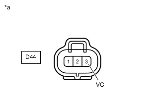
*a Front view of wire harness connector
(to Oil Pressure Sender Gauge Assembly)
-
Disconnect the oil pressure sender gauge assembly connector.
-
Turn the engine switch on (IG).
-
Measure the voltage according to the value(s) in the table below.
Standard Voltage Tester Connection Condition Specified Condition D44-3 (VC) - Body ground Engine switch on (IG) 4.75 to 5.25 V Result Proceed to OK NG
NG
CHECK HARNESS AND CONNECTOR (OIL PRESSURE SENDER GAUGE ASSEMBLY - ECM) Click here
OK
-
-
CHECK HARNESS AND CONNECTOR (OIL PRESSURE SENDER GAUGE ASSEMBLY - ECM)
-
Disconnect the oil pressure sender gauge assembly connector.
-
Disconnect the ECM connector.
-
Measure the resistance according to the value(s) in the table below.
Standard Resistance Tester Connection Condition Specified Condition D44-2 (PEO) - D1-98 (PEO) Always Below 1 Ω D44-1 (E2) - D1-129 (EPEO) Always Below 1 Ω D44-2 (PEO) or D1-98 (PEO) - Body ground and other terminals Always 10 kΩ or higher D44-1 (E2) or D1-129 (EPEO) - Body ground and other terminals Always 10 kΩ or higher Result Proceed to OK NG
OK
GO TO STEP 11 Click here
NG
REPAIR OR REPLACE HARNESS OR CONNECTOR
-
-
CHECK HARNESS AND CONNECTOR (OIL PRESSURE SENDER GAUGE ASSEMBLY - ECM)
-
Disconnect the oil pressure sender gauge assembly connector.
-
Disconnect the ECM connector.
-
Measure the resistance according to the value(s) in the table below.
Standard Resistance Tester Connection Condition Specified Condition D44-3 (VC) - D1-130 (VCPE) Always Below 1 Ω D44-3 (VC) or D1-130 (VCPE) - Body ground and other terminals Always 10 kΩ or higher Result Proceed to OK NG
OK
REPLACE ECM Click here
NG
REPAIR OR REPLACE HARNESS OR CONNECTOR
-
-
REPLACE OIL PRESSURE SENDER GAUGE ASSEMBLY
-
Replace the oil pressure sender gauge assembly.
Result Proceed to NEXT
NEXT
-
-
CHECK WHETHER DTC OUTPUT RECURS (DTC P052012, P052014, P052024, P05202A OR P052400)
-
Connect the GTS to the DLC3.
-
Turn the engine switch on (IG).
-
Turn the GTS on.
-
Clear the DTCs.
Powertrain > Engine > Clear DTCs -
Turn the engine switch off and wait for at least 30 seconds.
-
Start the engine.
-
Turn the GTS on.
-
Drive the vehicle in accordance with the driving pattern described in Confirmation Driving Pattern.
-
Enter the following menus: Powertrain / Engine / Trouble Codes.
-
Read the DTCs.
Powertrain > Engine > Trouble CodesResult Result Proceed to DTCs are not output A DTC P052012, P052014, P052024, P05202A or P052400 is output B
A
END
B
REPLACE ECM Click here
-