FUEL TANK(w/ Canister Pump Module) INSTALLATION
PROCEDURE
-
INSTALL TANK SUCTION TUBE SUPPORT
-
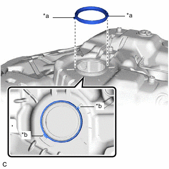
*a Protrusion *b Notch Install a new tank suction tube support to the fuel tank assembly.
Tech Tips
Align the protrusions of the tank suction tube support with the notches of the fuel tank assembly.
-
-
INSTALL FUEL TANK CUSHION SET
-
Install the 2 fuel tank cushion sets and 2 No. 5 fuel tank cushions to the fuel tank assembly.
-
-
INSTALL FUEL TANK MAIN TUBE SUB-ASSEMBLY
-
Engage the 3 claws to install the fuel tank main tube sub-assembly to the fuel tank assembly.
-
-
INSTALL REAR FUEL TANK SIDE PLATE
-
Install a new rear fuel tank side plate to the fuel tank assembly with the fuel tank cushion.
-
-
INSTALL FUEL TANK ASSEMBLY
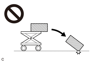
CAUTION:
The fuel tank assembly is very heavy. Be sure to follow the procedure described in the repair manual, or the fuel tank assembly may fall off the engine lifter.
-
Set the fuel tank assembly on an engine lifter.
Tech Tips
Using height adjustment attachments and plate lift attachments, keep the fuel tank assembly horizontal.
-
Using the engine lifter, slowly raise the fuel tank assembly, and then install the fuel tank assembly, No. 1 fuel tank band sub-assembly LH and No. 1 fuel tank band sub-assembly RH with the 4 bolts.
- Torque:
- 45 N*m { 459 kgf*cm, 33 ft.*lbf }
Note
-
Be careful not to drop the fuel tank assembly.
-
When installing the fuel tank assembly, tilt it slightly to prevent it from interfering with the surrounding parts.
-
Install the rear fuel tank bracket LH with the bolt and nut.
- Torque:
- Bolt
- 45 N*m { 459 kgf*cm, 33 ft.*lbf }
- Nut
- 19.6 N*m { 200 kgf*cm, 14 ft.*lbf }
-
Install the nut.
- Torque:
- 19.6 N*m { 200 kgf*cm, 14 ft.*lbf }
-
-
CONNECT FUEL TANK TO FILLER PIPE HOSE
-
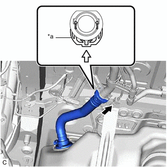
*a Retainer 
Push 
Push in Push the fuel tank to filler pipe hose to the fuel tank filler pipe assembly and push in the retainer to engage the lock claws.
Note
-
Check that there are no scratches or foreign matter around the connected parts of the fuel tank to filler pipe hose connector and fuel tank filler pipe assembly before performing this work.
-
After connecting the fuel tank to filler pipe hose, check that the fuel tank to filler pipe hose is securely connected by pulling on the fuel tank to filler pipe hose connector.
-
-
-
CONNECT FUEL TANK VENT HOSE SUB-ASSEMBLY
-
Connect the fuel tank vent hose sub-assembly to the charcoal canister assembly.
-
-
CONNECT FUEL TANK BREATHER TUBE
-
Connect the fuel tank breather tube to the fuel pipe.
-
-
CONNECT FUEL TANK MAIN TUBE SUB-ASSEMBLY
-
Connect the fuel tank main tube sub-assembly to the fuel pipe.
-
-
INSTALL NO. 1 FUEL TANK PROTECTOR SUB-ASSEMBLY
-
Install the No. 1 fuel tank protector sub-assembly with the 4 nuts and 4 new clips.
- Torque:
- 5.5 N*m { 56 kgf*cm, 49 in.*lbf }
-
-
INSTALL CHARCOAL CANISTER PROTECTOR
-
INSTALL FRONT CENTER FLOOR COVER
-
Engage the 4 clips to install the front center floor cover.
-
Install the 2 screws and nut.
-
-
INSTALL REAR SUSPENSION MEMBER SUB-ASSEMBLY (for 2WD)
-
INSTALL REAR SUSPENSION MEMBER SUB-ASSEMBLY (for AWD)
-
INSTALL FUEL SUCTION TUBE WITH PUMP AND GAUGE ASSEMBLY
-
ADD FUEL