ECD SYSTEM(w/ Urea SCR System) SYSTEM DESCRIPTION
-
ENGINE CONTROL SYSTEM
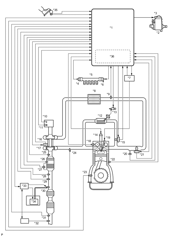
*1 ECM *2 Fuel Supply Pump Assembly *3 Pre-stroke Control Valve *4 Fuel Pressure Sensor *5 Common Rail Assembly *6 Pressure Discharge Valve *7 Glow Plug Controller *8 Intercooler Assembly *9 Intake Air Temperature Sensor (Turbo) *10 Mass Air Flow Meter Sub-assembly *11 Intake Air Temperature Sensor (Built Into Mass Air Flow Meter Sub-assembly) *12 No. 1 EGR Cooler *13 Vacuum Switching Valve Assembly (for EGR Bypass Valve) *14 Injector Assembly *15 Electric EGR Control Valve Assembly *16 Nozzle Vane Position Sensor *17 Variable Vane DC Motor *18 Camshaft Position Sensor *19 Glow Plug Assembly *20 Manifold Absolute Pressure Sensor *21 Diesel Throttle Body Assembly *22 Engine Coolant Temperature Sensor *23 Crankshaft Position Sensor *24 Exhaust Fuel Addition Injector Assembly *25 Exhaust Gas Temperature Sensor *26 No. 2 Exhaust Gas Temperature Sensor *27 Differential Pressure Sensor *28 No. 3 Exhaust Gas Temperature Sensor *29 Air Fuel Ratio Sensor *30 Urea Injector Set *31 No. 4 Exhaust Gas Temperature Sensor *32 Nitrogen Oxygen Sensor Assembly *33 Urea Pump Control ECU *34 Urea Pump *35 Accelerator Pedal Position Sensor *36 Atmospheric Pressure Sensor -
DIESEL PARTICULATE FILTER SYSTEM DESCRIPTION
-
Diesel Particulate Filter System comprehensively regulates engine control (consists of a catalytic system and a fuel injection system) that purifies particulate matter (PM) by diesel engines. The catalytic system purifies hydrocarbons (HC) and carbon monoxides (CO), and reduces PM with a catalytic converter with the Diesel Particulate Filter (DPF). The fuel injection system adds fuel into the exhaust port using the exhaust fuel addition injector to produce and maintain a proper catalyst temperature for PM forced regeneration.
-
DPF components:
Component Description DPF catalytic converter Reduces PM. DOC catalytic converter Reduces HC and CO. Exhaust fuel addition injector assembly Adds fuel into the exhaust port in order to raise catalyst temperature for PM forced regeneration.
-
Exhaust gas temperature sensor
-
No. 2 exhaust gas temperature sensor
-
No. 3 exhaust gas temperature sensor
Used for estimating the DPF catalytic converter temperature and adjusting fuel addition by ECM while PM forced regeneration is performed. Also detects the DPF catalytic converter temperature to prevent the catalytic converter temperature from rising too high. Differential pressure sensor Detects the volume of PM deposits and any incorrect air hose arrangement on the DPF catalytic converter. Air fuel ratio sensor Used for controlling the air-fuel ratio. By controlling the air-fuel ratio, combustion control and PM forced regeneration are properly regulated. -
-
Diagnostics Trouble Codes (DTCs) table for DPF:
Tech Tips
This table indicates typical DTC combinations for each malfunction occurrence.
Trouble Area Malfunction DTC No. DPF catalytic converter Deteriorated or clogged P0420*, P062F, P200C*, P200E*, P244A*, P244B*, P2458*, P2463* Exhaust fuel addition injector assembly Stuck open P20CF Stuck closed P0420*, P244A*, P2458* Low fuel addition volume P0420*, P244A*, P244B*, P2458*, P2463 Open in exhaust fuel addition injector circuit P0420*, P20CD, P244A*, P2458* Short in exhaust fuel addition injector circuit P0420*, P20CD, P20CF, P244A*, P2458* Open or short in exhaust fuel addition injector circuit P0420*, P200C*, P200E, P20CD*, P20CF, P244A*, P2458* Exhaust gas temperature sensor Open in exhaust gas temperature sensor circuit P0420*, P0545, P0546, P200C*, P200E*, P2032, P2033, P2080, P2084, P242B, P242C, P242D, P244A*, P2458* Short in exhaust gas temperature sensor circuit P0420*, P0545, P0546, P200C*, P200E*, P2032, P2033, P2080, P2084, P242B, P242C, P242D, P244A*, P2458* Exhaust gas temperature sensor P0420*, P0545, P0546, P200C*, P200E*, P2032, P2033, P2080, P2084, P242B, P242C, P242D, P244A*, P2458* Differential pressure sensor Open in differential pressure sensor circuit P0420*, P244A*, P2454, P2455, P2458*, P2463* Short in differential pressure sensor circuit P0420*, P244A*, P2454, P2455, P2458*, P2463* Differential pressure sensor P0420*, P244A*, P2454, P2455, P2458*, P2463* Differential pressure sensor clogged P0420*, P244A*, P2453, P2458*, P2463* Incorrect air hose arrangement of the differential pressure sensor P0420*, P244A*, P2453, P2458*, P2463* Air fuel ratio sensor Open or short in air fuel ratio sensor or heater circuit P0031, P0032, P2237, P2238, P2239, P2252, P2253, P244B*, P2463* Air fuel ratio sensor P0031, P0032, P2195, P2238, P2239, P2252, P2253, P244B*, P2463* Exhaust gas leaks Exhaust gas leaks P0420*, P244A*, P2458* Fuel leaks Fuel leaks in fuel addition injector P0420*, P200C*, P200E*, P20CF*, P244A*, P244B*, P2458*, P2463* Fuel supply pump assembly Correct fuel pressure cannot be fed to the exhaust fuel addition injector P0420*, P244A*, P244B*, P2458*, P2463* *: There may be no DTC output depending on the condition of the malfunction.
-
Diagnostics trouble code description for DPF:
DTC No. Description P0031 Open in air fuel ratio sensor heater control circuit (Low output) P0032 Short in air fuel ratio sensor or heater circuit (High output) P0420 DPF catalytic converter insufficient temperature increase P0545 Open or short in exhaust gas temperature sensor circuit (B1S1) (Low output) P0546 Open or short in exhaust gas temperature sensor circuit (B1S1) (High output) P200C DPF catalytic converter abnormally high exhaust gas temperature P200E Catalyst system temperature too high bank 1 P2032 Open or short in exhaust gas temperature sensor circuit (B1S2) (Low output) P2033 Open or short in exhaust gas temperature sensor circuit (B1S2) (High output) P2080 Exhaust gas temperature sensor circuit range/performance (B1S1) P2084 Exhaust gas temperature sensor circuit range/performance (B1S2) P20CD Open in exhaust fuel addition injector assembly circuit P20CF Exhaust fuel addition injector assembly stuck open P2195 Air fuel ratio sensor stuck lean P2237 Air fuel ratio sensor pumping current circuit/open P2238 Open or short in air fuel ratio sensor or heater circuit (Low output) P2239 Open or short in air fuel ratio sensor or heater circuit (High output) P2252 Open or short in air fuel ratio sensor or heater circuit (Low output) P2253 Open or short in air fuel ratio sensor or heater circuit (High output) P242B Exhaust gas temperature sensor circuit range / performance (B1S3) P242C Open or short in exhaust gas temperature sensor circuit (B1S3) (Low output) P242D Open or short in exhaust gas temperature sensor circuit (B1S3) (High output) P244A DPF catalytic converter excessive differential pressure (Low input) P244B DPF catalytic converter excessive differential pressure (High input) P2453 Differential pressure sensor is clogged or has incorrect air hose arrangement P2454 Open or short in differential pressure sensor circuit (Low output) P2455 Open or short in differential pressure sensor circuit (High output) P2458 Diesel particulate filter regeneration duration P2463 DPF catalytic converter soot deposition
-
-
UREA SCR SYSTEM
-
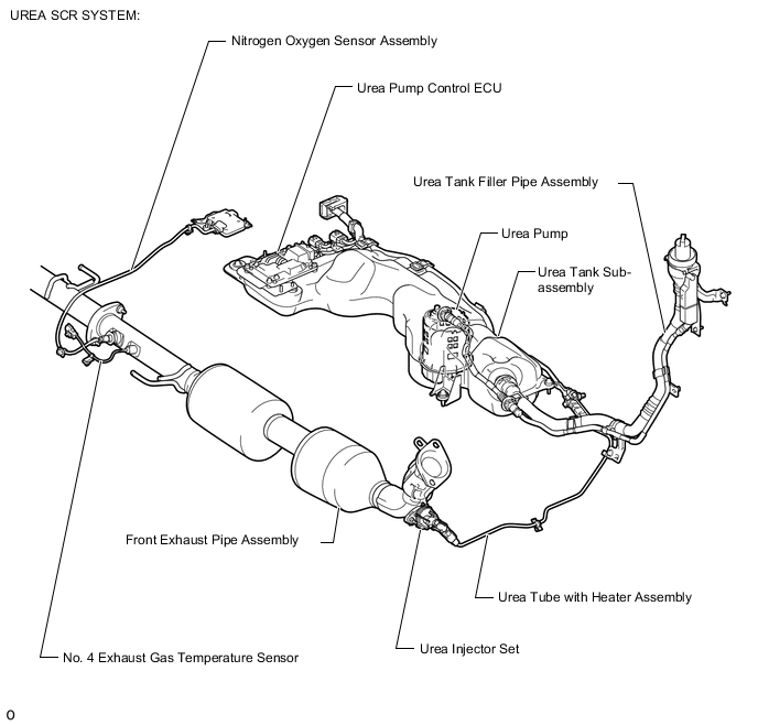
Urea SCR System:
(1) A urea SCR system is used to purify NOx in the exhaust gas. The urea SCR system injects urea solution into the exhaust gas to generate ammonia. The generated ammonia produces a chemical reaction with the NOx in the exhaust gas on the SCR catalyst, breaking it down into nitrogen and water, thereby purifying the exhaust gas.
(2) The urea SCR system is composed of a urea pump control ECU, urea tank sub-assembly, urea injector set, urea pump, No. 4 exhaust gas temperature sensor and nitrogen oxides sensor.
(3) In the urea SCR system, the urea pump control ECU controls the urea injector set and urea pump based on various signals.
-
Urea Pump:
(1) The urea pump has the following functions:
Function Outline Pump Function While performing feedback control according to the pressure sensor inside the urea pump, the pump raises the pressure to approximately 500 kPa, sending urea solution to the urea injector set. Heating Function The heater inside the urea pump is operated to thaw the urea solution so that exhaust gas can be purified even when the ambient temperature is low and the urea solution freezes. The heater turns on and off according to the urea solution temperature sensor inside the urea pump. Filter Function Foreign matter that enters the urea tank sub-assembly is collected by the filter inside the urea pump, preventing foreign matter from getting jammed in the urea pump and urea injector set. Level Gauge Function The fluid level position is detected by the float sensor inside the urea pump in order to detect the remaining quantity of urea solution inside the urea tank sub-assembly.
-
-
COMMON RAIL SYSTEM DESCRIPTION
-
Common rail system:
The common rail system uses high-pressure fuel for improved fuel economy. This system also provides robust engine power while suppressing engine vibration and noise.
This system stores fuel in the common rail, which has been pressurized and supplied by the fuel supply pump assembly. By storing fuel at high-pressure, the common rail system can provide fuel at stable fuel injection pressures, regardless of engine speed or engine load.
The ECM provides an electric current to the solenoid valve in each injector assembly to regulate the fuel injection timing and volume. The ECM also monitors the internal fuel pressure of the common rail using the fuel pressure sensor. The ECM causes the fuel supply pump assembly to supply the fuel necessary to obtain the target fuel pressure.
In addition, this system uses a solenoid valve inside each injector assembly to open and close the fuel passages. Therefore, both fuel injection time and fuel injection volume can be precisely regulated by the ECM.
The common rail system allows a multi stage fuel injection process. In order to soften combustion shock, this system performs "pilot-injection" prior to the "main-injection". This helps to reduce engine vibration and noise.
The system also performs "after-injection", which burns off fuel that was added during "pilot-injection" and "main-injection" and remained unburned, to increase the exhaust temperature for the DPF.
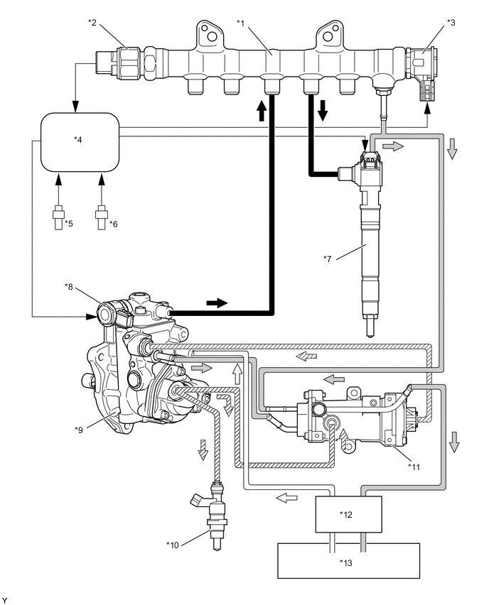
*1 Common Rail Assembly *2 Fuel Pressure Sensor *3 Pressure Discharge Valve *4 ECM *5 Crankshaft Position Sensor *6 Camshaft Position Sensor *7 Injector Assembly *8 Pre-stroke Control Valve *9 Fuel Supply Pump Assembly *10 Exhaust Fuel Addition Injector Assembly *11 Pressurized Fuel Filter *12 Fuel Filter Assembly *13 Fuel Tank Assembly - - 
Fuel (High Pressure) 
Fuel (Suction) 
Fuel (Feed Pressure) 
Fuel (Return) Tech Tips
If there is a problem with a fuel return pipe, the engine startability may deteriorate, as bleeding air from the fuel system may not be able to be performed properly in certain instances (such as after replacing an injector assembly).
-
Common rail system components:
Component Description Common rail assembly Stores high-pressure fuel produced by supply pump Fuel supply pump assembly
-
Operated by crankshaft via timing chain
-
Supplies high-pressure fuel to common rail
Injector assembly Injects fuel to combustion chamber based on signals from ECM Fuel pressure sensor Monitors internal fuel pressure of common rail and sends signals to ECM Pressure discharge valve Based on signals from ECM, opens valve when sudden deceleration occurs, or when ignition switch is off to prevent fuel pressure from becoming too high Pre-stroke control valve Based on signals from ECM, adjusts fuel volume supplied to common rail and regulates internal fuel pressure -
-
Diagnostic trouble code (DTC) table for the common rail system:
Tech Tips
This table indicates typical DTC combinations for each malfunction occurrence.
Trouble Area Malfunction DTC No. Injector assembly Open or short in injector circuit P0093*, P0201, P0202, P0203, P0204 Stuck open P0093 Stuck closed P0301, P0302, P0303, P0304 Fuel pressure sensor Open or short in fuel pressure sensor circuit or pressure sensor output fixed P0087, P0190, P0191, P0192, P0193 Pressure discharge valve Open or short in pressure discharge valve circuit P0088*, P0093*, P1229*, P1271, P1272 Stuck open P0093 Stuck closed P0088*, P1272 Pre-stroke control valve Open or short in pre-stroke control valve circuit P0627, P1229, P0088* Stuck open P0088*, P1229 Common rail system (Fuel system) Fuel leaks in high-pressure area P0093 *: There may be no DTC output depending on the condition of the malfunction.
-
Diagnostic trouble code description for the common rail system:
DTC No. Description P0087 Fuel pressure sensor output does not change P0088 Internal fuel pressure too high (240000 kPa [2447 kgf/cm2, 34800 psi] or more)
P0093 Fuel leaks in high-pressure areas P0190 Open or short in fuel pressure sensor circuit (output voltage is too low or too high) P0191 Fuel pressure sensor circuit output fixed P0192 Open or short in fuel pressure sensor circuit (output voltage is too low) P0193 Open or short in fuel pressure sensor circuit (output voltage is too high) P0201 Open or short in No. 1 injector circuit P0202 Open or short in No. 2 injector circuit P0203 Open or short in No. 3 injector circuit P0204 Open or short in No. 4 injector circuit P0301 Cylinder 1 misfire detected P0302 Cylinder 2 misfire detected P0303 Cylinder 3 misfire detected P0304 Cylinder 4 misfire detected P0627 Open or short in pre-stroke control valve circuit P062D ECM internal error P1229 Fuel over-feed P1271 Open or short in pressure discharge valve circuit P1272 Pressure discharge valve stuck close
-
-
FUEL SUPPLY PUMP OPERATION SYSTEM DESCRIPTION
-
When the cam rotates the roller is pushed up, and in turn the plunger is pushed upward as well. When the plunger is not pushed up by the cam, it is pushed back down by the spring.
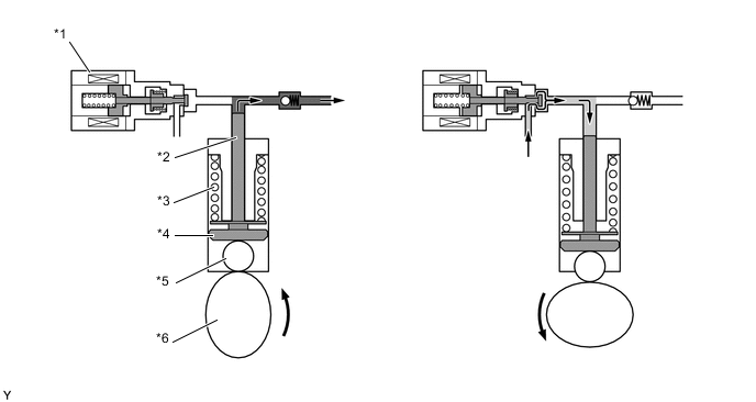
*1 Pre-stroke Control Valve *2 Plunger *3 Spring *4 Shoe *5 Roller *6 Double Cam -
The ECM controls the timing of the pre-stroke control valve opening to regulate the fuel quantity. Consequently, the fuel pressure in the common rail is controlled to the target injection pressure.
-
The longer the pre-stroke control valve remains open, the quantity of pressure-fed strokes will decrease, as well as the fuel discharge quantity.
-
Pumping will start when the fuel pressure has become higher than the common rail pressure.
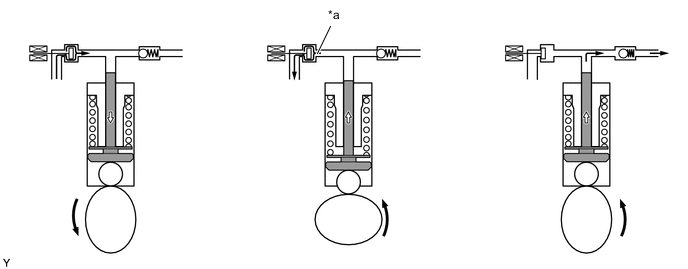
*a Return Fuel - - -
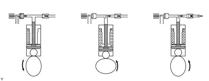
The less time the pre-stroke control valve remains open, the quantity of pressure-fed strokes will increase, as well as the fuel discharge quantity.
-
Pumping will start when the fuel pressure has become higher than the common rail pressure.
-