TRANSFER ASSEMBLY REASSEMBLY

PROCEDURE
-
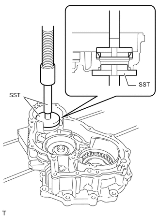
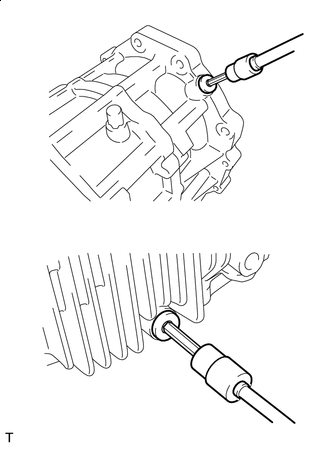
INSTALL TRANSFER FRONT DRIVE GEAR ASSEMBLY CYLINDRICAL ROLLER BEARING
-
for Rear transfer case side:
-
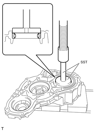
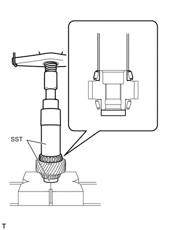
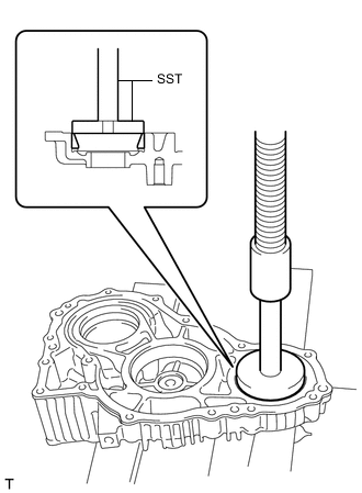
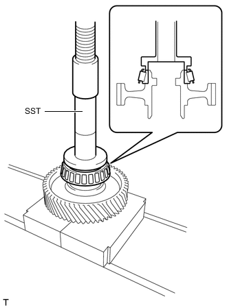
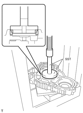
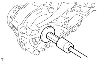
Using SST and a press, install a new transfer front drive gear assembly cylindrical roller bearing to the rear transfer case.
- SST
- 09950-60021 ( 09951-00710 )
- 09950-70010 ( 09951-07100 )
Note
-
Securely install so that it contacts the end of the rear transfer case.
-
Be careful of the straight pins when placing the case on the press.
-
Be careful not to damage the rear transfer case.
-
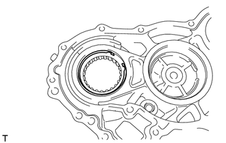
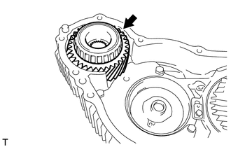
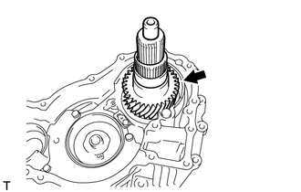
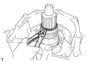
Using needle-nose pliers, install the transfer front drive gear snap ring to the rear transfer case.
-
-
for Front transfer case side:
-
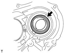
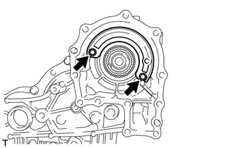
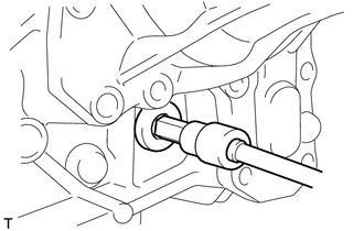
Install the transfer front drive gear bearing and No. 3 transfer thrust bearing race to the front transfer case.
-
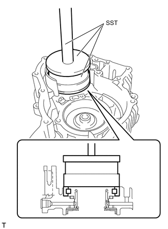
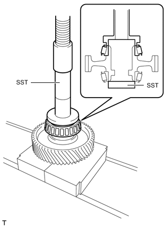
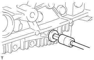
Using SST and a press, install a new transfer front drive gear assembly cylindrical roller bearing to the front transfer case.
- SST
- 09527-17011
- 09951-01000
- 09950-70010 ( 09951-07150 )
Note
-
Securely install so that it contacts the end of the front transfer case.
-
Be careful not to damage the rear transfer case.
-
-
-
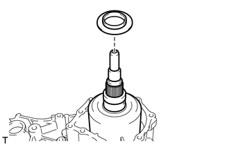
INSTALL TRANSFER FRONT CASE OIL SEAL
-
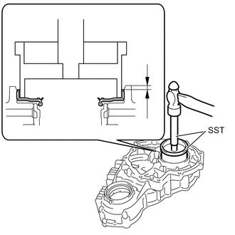
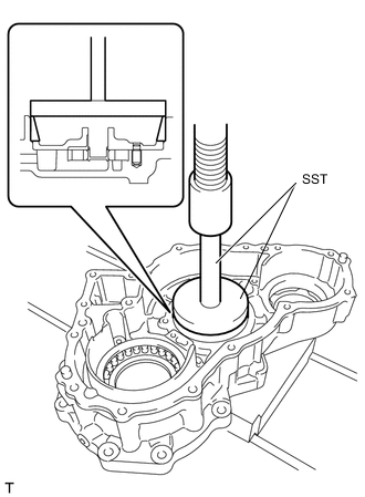
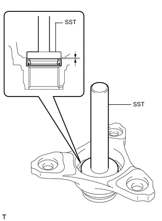
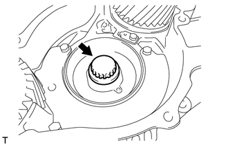
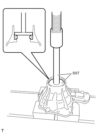
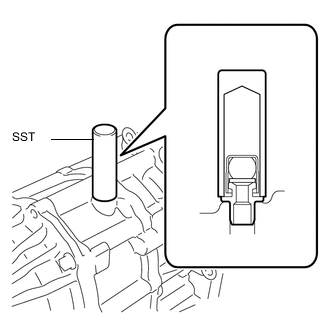
Using SST and a hammer, tap a new transfer front case oil seal into the front transfer case up to the standard value as shown in the illustration.
- SST
- 09223-15020
- 09950-70010 ( 09951-07100 )
Standard depth 1.0 to 1.5 mm (0.0394 to 0.0590 in.) Note
-
Tap the transfer front case oil seal evenly so that the oil seal is straight.
-
Do not excessively tap the transfer front case oil seal.
-
Apply a small amount of MP grease No. 2 to the lip of the transfer front case oil seal.
-
-
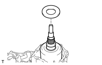
INSTALL TRANSFER OUTPUT SHAFT COMPANION FLANGE OIL SEAL
-
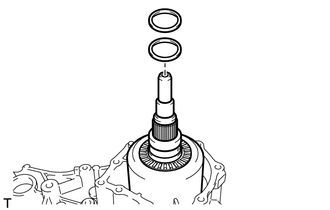
INSTALL FORWARD CLUTCH DRUM OIL SEAL RING
-
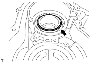
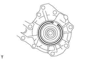
Install the forward clutch drum oil seal ring to the front transfer case.
-
-
INSTALL TRANSFER COUNTER GEAR BEARING (for Front Transfer Case Side)
-
for Front transfer case side:
-
Using SST and a press, install a new transfer counter gear bearing (outer race) to the front transfer case.
- SST
- 09950-60011 ( 09951-00580, 09951-00610, 09952-06010 )
- 09950-60021 ( 09951-00730, 09951-00790, 09952-06010 )
- 09950-70010 ( 09951-07100 )
Note
-
Securely install so that it contacts the end of the front transfer case.
-
Be careful not to damage the front transfer case.
-
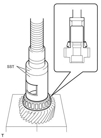
Using SST and a press, install a new transfer counter gear bearing (inner race) to the front transfer case.
- SST
- 09612-24014 ( 09613-22011 )
- 09950-60011 ( 09951-00340, 09951-00510, 09952-06010 )
Note
-
Securely install so that it contacts the end of the transfer counter gear.
-
Be careful not to damage the transfer counter gear.
Tech Tips
Disassemble SST (09613-22011), and only use the pipe part.
-
-
for Rear transfer case side:
-
Using SST and a press, install a new transfer counter gear bearing (inner race) to the front transfer case.
- SST
- 09316-60012 ( 09316-00011 )
- 09950-60011 ( 09951-00420 )
Note
-
Securely install so that it contacts the end of the transfer counter gear.
-
Be careful not to damage the transfer counter gear.
Tech Tips
Install the transfer counter gear bearing (outer race) when adjusting the counter gear bearing preload.
-
-
-
ADJUST COUNTER GEAR BEARING PRELOAD
-
Install the transfer counter gear assembly to the front transfer case.
-
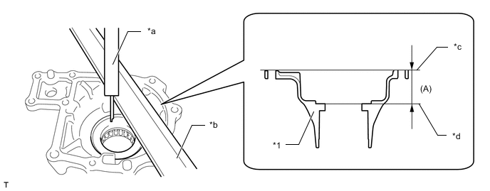
Using a vernier caliper and straightedge, measure the dimension (A) between the contact surface of the front transfer case and the end of the transfer counter gear bearing (outer race) with a load applied.
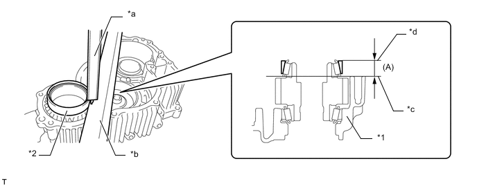
*1 Front Transfer Case *2 Transfer Counter Gear Bearing (Outer Race) *a Vernier Caliper *b Precision Straightedge *c Transfer Case Contact Surface *d Transfer Counter Gear Bearing (Outer Race) End Note
-
Before measuring, clean the contact surface of the transfer case so that there is no foreign matter.
-
Measure the transfer idler gear while it is uninstalled.
-
Do not add the thickness of the straightedge.
Tech Tips
Perform the measurement at 3 locations at intervals of 120° around the circumference of the outer race and calculate the average.
-
-
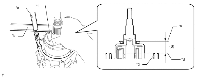
Using a vernier caliper and straightedge, measure the dimension (B) from the contact surface of the rear transfer case and front transfer case to the shim installation surface of the transfer counter gear assembly.
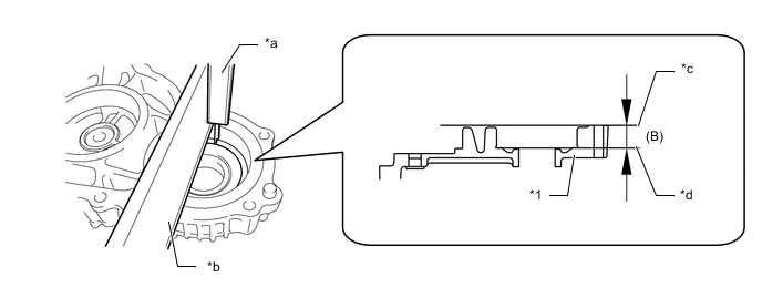
*1 Rear Transfer Case - - *a Vernier Caliper *b Precision Straightedge *c Rear Transfer Case and Front Transfer Case Contact Surface *d Transfer Counter Gear Assembly Shim Installation Surface Note
Do not add the thickness of the precision straightedge.
-
Using the formula below, calculate the thickness of the transfer counter gear shim and select an appropriate shim from the table.
Transfer counter gear shim thickness Dimension B - Dimension A Transfer Counter Gear Shim Thickness Identification Mark Thickness Identification Mark Thickness Identification Mark Thickness 40 1.39 to 1.41 mm (0.0548 to 0.0555 in.) 72 1.71 to 1.73 mm (0.0674 to 0.0681 in.) 04 2.03 to 2.05 mm (0.0800 to 0.0807 in.) 42 1.41 to 1.43 mm (0.0556 to 0.0562 in.) 74 1.73 to 1.75 mm (0.0682 to 0.0688 in.) 06 2.05 to 2.07 mm (0.0808 to 0.0814 in.) 44 1.43 to 1.45 mm (0.0563 to 0.0570 in.) 76 1.75 to 1.77 mm (0.0689 to 0.0696 in.) 08 2.07 to 2.09 mm (0.0815 to 0.0822 in.) 46 1.45 to 1.47 mm (0.0571 to 0.0578 in.) 78 1.77 to 1.79 mm (0.0697 to 0.0704 in.) 10 2.09 to 2.11 mm (0.0823 to 0.0830 in.) 48 1.47 to 1.49 mm (0.0579 to 0.0586 in.) 80 1.79 to 1.81 mm (0.0705 to 0.0712 in.) 12 2.11 to 2.13 mm (0.0831 to 0.0838 in.) 50 1.49 to 1.51 mm (0.0587 to 0.0594 in.) 82 1.81 to 1.83 mm (0.0713 to 0.0720 in.) 14 2.13 to 2.15 mm (0.0839 to 0.0846 in.) 52 1.51 to 1.53 mm (0.0595 to 0.0602 in.) 84 1.83 to 1.85 mm (0.0721 to 0.0728 in.) 16 2.15 to 2.17 mm (0.0847 to 0.0854 in.) 54 1.53 to 1.55 mm (0.0603 to 0.0610 in.) 86 1.85 to 1.87 mm (0.0729 to 0.0736 in.) 18 2.17 to 2.19 mm (0.0855 to 0.0862 in.) 56 1.55 to 1.57 mm (0.0611 to 0.0618 in.) 88 1.87 to 1.89 mm (0.0737 to 0.0744 in.) 20 2.19 to 2.21 mm (0.0863 to 0.0870 in.) 58 1.57 to 1.59 mm (0.0619 to 0.0625 in.) 90 1.89 to 1.91 mm (0.0745 to 0.0751 in.) 22 2.21 to 2.23 mm (0.0871 to 0.0877 in.) 60 1.59 to 1.61 mm (0.0626 to 0.0633 in.) 92 1.91 to 1.93 mm (0.0752 to 0.0759 in.) 24 2.23 to 2.25 mm (0.0878 to 0.0885 in.) 62 1.61 to 1.63 mm (0.0634 to 0.0641 in.) 94 1.93 to 1.95 mm (0.0760 to 0.0767 in.) 26 2.25 to 2.27 mm (0.0886 to 0.0893 in.) 64 1.63 to 1.65 mm (0.0642 to 0.0649 in.) 96 1.95 to 1.97 mm (0.0768 to 0.0775 in.) 28 2.27 to 2.29 mm (0.0894 to 0.0901 in.) 66 1.65 to 1.67 mm (0.0650 to 0.0657 in.) 98 1.97 to 1.99 mm (0.0776 to 0.0783 in.) 30 2.29 to 2.31 mm (0.0902 to 0.0909 in.) 68 1.67 to 1.69 mm (0.0658 to 0.0665 in.) 00 1.99 to 2.01 mm (0.0784 to 0.0791 in.) - - 70 1.69 to 1.71 mm (0.0666 to 0.0673 in.) 02 2.01 to 2.03 mm (0.0792 to 0.0799 in.) - - -
Using SST and a press, install the shim and a new transfer counter gear bearing (outer race) to the rear transfer case.
- SST
- 09950-60021 ( 09951-00750 )
- 09950-70010 ( 09951-07100 )
Note
-
Securely install so that it contacts the end of the rear transfer case.
-
Be careful not to damage the rear transfer case.
-
Install the rear transfer case.
-
Clean and degrease the rear transfer case and front transfer case installation bolt holes.
-
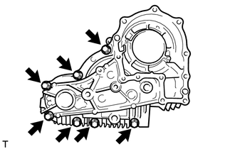
Install the rear transfer case with the 7 bolts to the front transfer case.
- Torque:
- 29 N*m { 296 kgf*cm, 21 ft.*lbf }
Bolt Length Beneath Head Bolt Type Bolt Length Beneath Head Bolt A 55 mm (2.17 in.) Bolt B 45 mm (1.77 in.)
-
-
Install the output shaft companion flange sub-assembly.
-
Rotate the transfer counter gear assembly forwards and backwards to fit the transfer counter gear bearing.
-
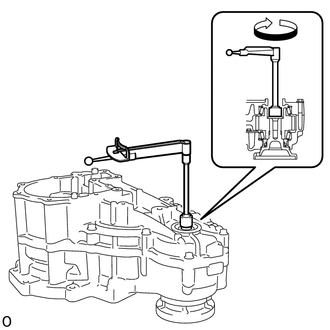
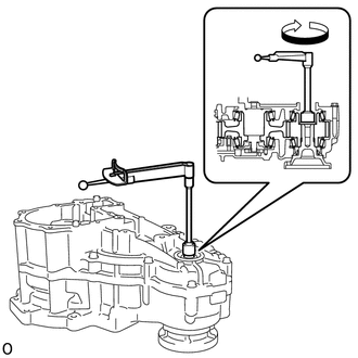
Using a torque wrench, check the torque (counter gear preload) of the transfer counter gear bearing.
Standard turning torque 0.66 to 1.18 N*m (7 to 12 kgf*cm, 6 to 10 in.*lbf) Note
Measure the transfer idler gear while it is uninstalled.
Tech Tips
Measure the torque at approximately 60 r/min (1 rotation/second).
If the result is not as specified, select the transfer counter gear assembly shim and adjust.
-
Remove the output shaft companion flange sub-assembly.
-
Remove the 7 bolts and the rear transfer case cover from the front transfer case.
-
Remove the transfer counter gear assembly from the front transfer case.
-
-
INSTALL TRANSFER OIL PUMP PLATE SUB-ASSEMBLY
-
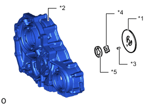
*1 Transfer Oil Pump Plate Sub-assembly *2 Front Transfer Case *3 Transfer Oil Pump Plate Pin *4 Transfer Oil Pump Drive Rotor *5 Transfer Oil Pump Driven Rotor Install the drive rotor and driven rotor to the front transfer case.
-
Install the plate pin to the oil pump plate.
-
Install the plate to the front transfer case.
Note
Align the position of transfer oil pump plate pin with the front transfer case and install it.
-
-
INSTALL TRANSFER IDLER GEAR BEARING (for Front Transfer Case Side)
-
for Front transfer case side:
-
Using SST and a press, install a new transfer idler gear bearing (outer race) to the front transfer case.
- SST
- 09950-60021 ( 09951-00890 )
- 09950-70010 ( 09951-07100 )
Note
-
Securely install so that it contacts the end of the front transfer case.
-
Be careful not to damage the front transfer case.
-
Using SST and a press, install a new transfer idler gear bearing (inner race) to the front transfer case.
- SST
- 09554-22010
Note
-
Securely install so that it contacts the end of the transfer idler gear.
-
Be careful not to damage the transfer idler gear bearing.
-
-
for Rear transfer case side:
-
Using SST and a press, install a new transfer idler gear bearing (inner race) to the front transfer case.
- SST
- 09554-22010
- 09950-60011 ( 09951-00540 )
Note
-
Securely install so that it contacts the end of the transfer idler gear.
-
Be careful not to damage the transfer idler gear.
Tech Tips
Install the transfer idler gear bearing (outer race) when adjusting the idler gear bearing preload.
-
-
-
ADJUST IDLER GEAR
-
Install the transfer counter gear assembly to the front transfer case.
-
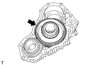
Install the transfer idler gear assembly to the front transfer case.
-
Using a vernier caliper and straightedge, measure the dimension (A) between the contact surface of the front transfer case and the end of the transfer idler gear bearing (outer race) with a load applied.
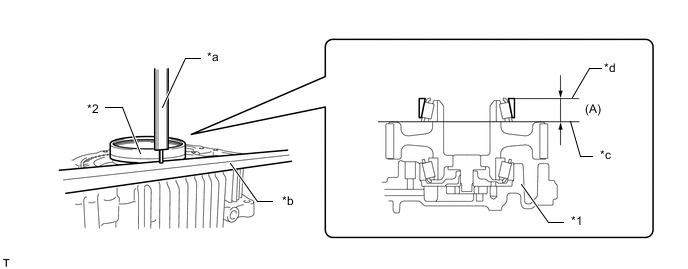
*1 Front Transfer Case *2 Transfer Idler Gear Bearing (Outer Race) *a Vernier Caliper *b Precision Straightedge *c Transfer Case Contact Surface *d Transfer Idler Gear Bearing (Outer Race) End Note
-
Before measuring, clean the contact surface of the transfer case so that there is no foreign matter.
-
Do not add the thickness of the straightedge.
Tech Tips
Measure the 3 places every 120° from any point on the circumference of the transfer idler gear bearing (outer race), and use the average value.
-
-
Using a vernier caliper and straightedge, measure the dimension (B) from the contact surface of the rear transfer case and front transfer case to the shim installation surface of the transfer idler gear.
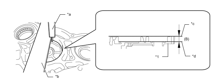
*1 Rear Transfer Case - - *a Vernier Caliper *b Precision Straightedge *c Rear Transfer Case and Front Transfer Case Contact Surface *d Transfer Idler Gear Shim Installation Surface Note
-
Before measuring, clean the contact surface of the transfer case so that there is no foreign matter.
-
Do not add the thickness of the straightedge.
-
-
Using the following formula, calculate the plate thickness of the transfer idler gear shim and select from the table.
Transfer Idler Gear Shim Thickness Dimension (B) - Dimension (A) Transfer Idler Gear Shim Type Identification Mark Thickness (mm) Identification Mark Thickness (mm) Identification Mark Thickness (mm) 90 0.89 to 0.91 mm (0.0351 to 0.0358 in.) 22 1.21 to 1.23 mm (0.0477 to 0.0484 in.) 54 1.53 to 1.55 mm (0.0603 to 0.0610 in.) 92 0.91 to 0.93 mm (0.0359 to 0.0366 in.) 24 1.23 to 1.25 mm (0.0485 to 0.0492 in.) 56 1.55 to 1.57 mm (0.0611 to 0.0618 in.) 94 0.93 to 0.95 mm (0.0367 to 0.0374 in.) 26 1.25 to 1.27 mm (0.0493 to 0.0499 in.) 58 1.57 to 1.59 mm (0.0619 to 0.0625 in.) 96 0.95 to 0.97 mm (0.0375 to 0.0381 in.) 28 1.27 to 1.29 mm (0.0500 to 0.0507 in.) 60 1.59 to 1.61 mm (0.0626 to 0.0633 in.) 98 0.97 to 0.99 mm (0.0382 to 0.0389 in.) 30 1.29 to 1.31 mm (0.0508 to 0.0515 in.) 62 1.61 to 1.63 mm (0.0634 to 0.0641 in.) 00 0.99 to 1.01 mm (0.0390 to 0.0397 in.) 32 1.31 to 1.33 mm (0.0516 to 0.0523 in.) 64 1.63 to 1.65 mm (0.0642 to 0.0649 in.) 02 1.01 to 1.03 mm (0.0398 to 0.0405 in.) 34 1.33 to 1.35 mm (0.0524 to 0.0531 in.) 66 1.65 to 1.67 mm (0.0650 to 0.0657 in.) 04 1.03 to 1.05 mm (0.0406 to 0.0413 in.) 36 1.35 to 1.37 mm (0.0532 to 0.0539 in.) 68 1.67 to 1.69 mm (0.0658 to 0.0665 in.) 06 1.05 to 1.07 mm (0.0414 to 0.0421 in.) 38 1.37 to 1.39 mm (0.0540 to 0.0547 in.) 70 1.69 to 1.71 mm (0.0666 to 0.0673 in.) 08 1.07 to 1.09 mm (0.0422 to 0.0429 in.) 40 1.39 to 1.41 mm (0.0548 to 0.0555 in.) 72 1.71 to 1.73 mm (0.0674 to 0.0681 in.) 10 1.09 to 1.11 mm (0.0430 to 0.0437 in.) 42 1.41 to 1.43 mm (0.0556 to 0.0562 in.) 74 1.73 to 1.75 mm (0.0682 to 0.0688 in.) 12 1.11 to 1.13 mm (0.0438 to 0.0444 in.) 44 1.43 to 1.45 mm (0.0563 to 0.0570 in.) 76 1.75 to 1.77 mm (0.0689 to 0.0696 in.) 14 1.13 to 1.15 mm (0.0445 to 0.0452 in.) 46 1.45 to 1.47 mm (0.0571 to 0.0578 in.) 78 1.77 to 1.79 mm (0.0697 to 0.0704 in.) 16 1.15 to 1.17 mm (0.0453 to 0.0460 in.) 48 1.47 to 1.49 mm (0.0579 to 0.0586 in.) 80 1.79 to 1.81 mm (0.0705 to 0.0712 in.) 18 1.17 to 1.19 mm (0.0461 to 0.0468 in.) 50 1.49 to 1.51 mm (0.0587 to 0.0594 in.) - - 20 1.19 to 1.21 mm (0.0469 to 0.0476 in.) 52 1.51 to 1.53 mm (0.0595 to 0.0602 in.) - - -
Using SST and a press, install a new transfer idler gear bearing (outer race) and transfer idler gear shim to the rear transfer case.
- SST
- 09950-60021 ( 09951-00780, 09951-00890, 09952-06010 )
- 09950-70010 ( 09951-07100 )
Note
-
Securely install so that it contacts the end of the rear transfer case.
-
Be careful not to damage the rear transfer case.
-
Install the rear transfer case
-
Clean and degrease the rear transfer case and front transfer case installation bolt holes.
-
Install the rear transfer case with the 7 bolts to the front transfer case.
- Torque:
- 29 N*m { 296 kgf*cm, 21 ft.*lbf }
Bolt Length Beneath Head Bolt Type Bolt Length Beneath Head Bolt A 55 mm (2.17 in.) Bolt B 45 mm (1.77 in.)
-
-
Install the output shaft companion flange sub-assembly.
-
Rotate the transfer idler gear forwards and backwards to fit the transfer idler gear bearing.
-
Using a torque wrench, check the torque (idler gear preload) of the transfer idler gear bearing.
Standard turning torque 1.54 to 2.64 N*m (16 to 26 kgf*cm, 14 to 23 in.*lbf) Note
Use the measured torque of the idler gear preload as the total preload for the transfer idler gear and transfer counter gear assembly.
Tech Tips
Measure the torque at approximately 60 r/min (1 rotation/second).
-
If the result is not as specified, select the transfer idler gear shim and adjust.
-
Remove the output shaft companion flange sub-assembly.
-
Remove the 7 bolts and the rear transfer case cover from the front transfer case.
-
Remove the transfer idler gear assembly from the front transfer case.
-
Remove the transfer counter gear assembly from the front transfer case.
-
-
INSTALL NO. 1 TRANSFER OIL STRAINER
-
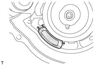
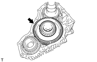
Install the No. 1 transfer oil strainer to the front transfer case.
-
-
INSTALL TRANSFER OIL SEPARATOR
-
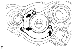
Install the transfer oil separator with the 3 bolts.
- Torque:
- 7.0 N*m { 71 kgf*cm, 62 in.*lbf }
-
-
INSTALL DRIVE PINION COMPANION FLANGE OIL SEAL
-
Using SST and a hammer, tap a new drive pinion companion flange oil seal up to the standard value.
- SST
- 09950-60011 ( 09951-00350 )
- 09950-70010 ( 09951-07100 )
Standard oil seal depth 0 to 0.3 mm (0 to 0.0118 in.) Note
-
Tap in the drive pinion companion flange oil seal evenly so that the drive pinion companion flange oil seal is straight.
-
Do not excessively tap in the drive pinion companion flange oil seal.
-
Apply a small amount of MP grease to the lip of the drive pinion companion flange oil seal.
-
-
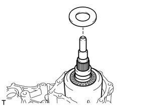
INSTALL TRANSFER OIL SEAL RING
-
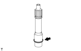
Install the transfer oil seal ring to the transfer input shaft.
Note
Do not excessively widen the transfer oil seal ring.
-
-
INSTALL TRANSFER INPUT SHAFT
-
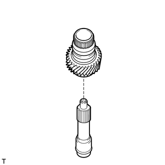
Install the transfer input shaft to the transfer front drive gear assembly.
-
-
INSTALL TRANSFER FRONT DRIVE GEAR PIN
-
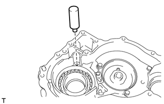
Install the transfer front drive gear pin to the front transfer case.
-
-
INSTALL TRANSFER FRONT DRIVE GEAR ASSEMBLY
-
Install the transfer front drive gear assembly and transfer input shaft to the front transfer case.
-
-
INSTALL TRANSFER COUNTER GEAR ASSEMBLY
-
Install the transfer counter gear assembly to the front transfer case.
-
-
INSTALL TRANSFER OIL PUMP DRIVE SHAFT
-
Install the transfer oil pump drive shaft to the front transfer case.
-
-
INSTALL TRANSFER IDLER GEAR ASSEMBLY
-
Install the transfer idler gear assembly to the front transfer case.
-
-
INSTALL REAR TRANSFER CASE
-
Clean the bolt holes of the front transfer case.
-
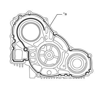
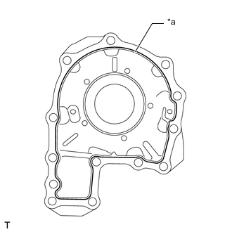
*a Seal Packing 1281 (Approximately 1.2 mm diameter) Apply seal packing 1281 (approximately 1.2 mm diameter) to the points shown in the illustration.
Note
Clean and degrease the installation surface.
-
Install the rear transfer case with the 7 bolts to the front transfer case.
- Torque:
- 29 N*m { 296 kgf*cm, 21 ft.*lbf }
Bolt Length Beneath Head Bolt Type Bolt Length Beneath Head Bolt A 55 mm (2.17 in.) Bolt B 45 mm (1.77 in.) Note
Tighten the bolts within 10 minutes after applying the seal packing.
-
-
INSTALL TRANSFER INPUT GEAR STOPPER
-
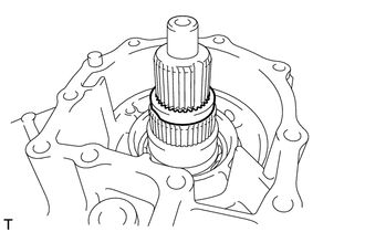
Install the transfer input gear stopper to the transfer input shaft.
-
-
INSTALL TRANSFER INPUT GEAR STOPPER SHAFT SNAP RING
-
Using a snap ring expander, install the transfer input gear stopper shaft snap ring to the transfer input shaft.
-
-
INSTALL BREATHER OIL DEFLECTOR
-
Install the breather oil deflector with the 2 bolts to the rear transfer case.
- Torque:
- 7.0 N*m { 71 kgf*cm, 62 in.*lbf }
-
-
INSTALL TRANSFER OUTPUT SHAFT CYLINDRICAL ROLLER BEARING
-
Using SST and a press, install a new transfer output shaft cylindrical roller bearing to the transfer extension housing.
- SST
- 09950-60011 ( 09951-00600 )
- 09950-70010 ( 09951-07100 )
Note
-
Securely install so that it contacts the end of the transfer extension housing.
-
Be careful not to damage the transfer extension housing.
-
-
INSTALL NO. 1 DIFFERENTIAL CASE SUB-ASSEMBLY HOLE SNAP RING
-
Using needle-nose pliers, install the differential case sub-assembly No. 1 hole snap ring to the transfer extension housing.
-
-
INSTALL NO. 1 DIFFERENTIAL CASE SUB-ASSEMBLY
-
Install the No. 1 differential case sub-assembly to the rear transfer case.
-
-
INSTALL TRANSFER OUTPUT SHAFT SHIM
-
Install the transfer output shaft shim to the No. 1 differential case sub-assembly.
-
-
INSTALL NO. 2 TRANSFER THRUST BEARING RACE
-
Install the No. 2 transfer thrust bearing race to the No. 1 differential case sub-assembly.
Note
Make sure to install the No. 2 transfer thrust bearing race in the correct direction.
-
-
INSTALL DIFFERENTIAL CASE NEEDLE ROLLER BEARING
-

Install the differential case needle roller bearing to the No. 1 differential case sub-assembly.
Note
Make sure to install the differential case needle roller bearing in the correct direction.
-
-
INSTALL TRANSFER OUTPUT SHAFT WASHER
-
Install the 2 transfer output shaft washers to the No. 1 differential case sub-assembly.
-
-
INSTALL NO. 1 TRANSFER THRUST BEARING RACE
-
Install the No. 1 transfer thrust bearing race to the No. 1 differential case sub-assembly.
-
-
ADJUST TRANSFER OUTPUT SHAFT SHIM
-
Using a vernier caliper and straightedge, measure the dimension (A) between the contact surface of the transfer extension housing and the installation surface of the No. 1 transfer thrust bearing race.
*1 Transfer Extension Housing - - *a Vernier Caliper *b Precision Straightedge *c Transfer Extension Housing Contact Surface *d No. 1 Transfer Thrust Bearing Race Installation Surface Note
-
Before measuring, clean the contact surface of the transfer case so that there is no foreign matter.
-
Do not add the thickness of the straightedge.
-
-
Using a vernier caliper and straightedge, measure the dimension (B) from the No. 1 transfer thrust bearing race to the extension housing connection surface of the rear transfer case.
*1 No. 1 Transfer Thrust Bearing Race *2 Rear Transfer Case *a Vernier Caliper *b Precision Straightedge *c No. 1 Transfer Thrust Bearing Race *d Rear Transfer Case Extension Housing Contact Surface Note
Do not add the thickness of the straightedge.
-
Using the following formula, calculate the plate thickness of the transfer output shaft shim and select from the table.
Transfer output shim thickness Dimension A - Dimension B Transfer Output Shim Thickness Mark Specified Condition Mark Specified Condition 98 0.96 to 1.00 mm (0.0378 to 0.0393 in.) 43 1.41 to 1.45 mm (0.0556 to 0.0570 in.) 03 1.01 to 1.05 mm (0.0398 to 0.0413 in.) 48 1.46 to 1.50 mm (0.0575 to 0.0590 in.) 08 1.06 to 1.10 mm (0.0418 to 0.0433 in.) 53 1.51 to 1.55 mm (0.0595 to 0.0610 in.) 13 1.11 to 1.15 mm (0.0438 to 0.0452 in.) 58 1.56 to 1.60 mm (0.0615 to 0.0629 in.) 18 1.16 to 1.20 mm (0.0457 to 0.0472 in.) 63 1.61 to 1.65 mm (0.0634 to 0.0649 in.) 23 1.21 to 1.25 mm (0.0477 to 0.0492 in.) 68 1.66 to 1.70 mm (0.0654 to 0.0669 in.) 28 1.26 to 1.30 mm (0.0497 to 0.0511 in.) 73 1.71 to 1.75 mm (0.0674 to 0.0688 in.) 33 1.31 to 1.35 mm (0.0516 to 0.0531 in.) 78 1.76 to 1.80 mm (0.0693 to 0.0708 in.) 38 1.36 to 1.40 mm (0.0536 to 0.0551 in.) - -
-
-
INSTALL TRANSFER EXTENSION HOUSING
-
Clean and degrease the rear transfer case transfer extension housing installation bolt holes.
-
*a Seal Packing 1281 (Approximately 1.2 mm diameter) Apply seal packing 1281 (approximately 1.2 mm diameter) to the points shown in the illustration.
Note
Clean and degrease the installation surface.
-
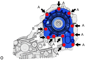
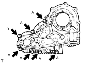
Install the transfer extension housing and bracket to the transfer case with the 8 bolts (A) and 3 new bolts (B).
- Torque:
- 29 N*m { 296 kgf*cm, 21 ft.*lbf }
Bolt Length Beneath Head Bolt Type Bolt length beneath head Bolt A 112 mm (4.41 in.) Bolt B 35 mm (1.38 in.) Note
Tighten the bolts within 10 minutes after applying the seal packing.
-
-
INSTALL TRANSFER EXTENSION HOUSING OIL SEAL
-
INSTALL DRIVE PINION COMPANION FLANGE SUB-ASSEMBLY
-
INSTALL OUTPUT SHAFT COMPANION FLANGE SUB-ASSEMBLY
-
INSTALL NO. 2 TRANSFER CASE PLUG
-
Using a 17 mm straight hexagon wrench, install a new gasket and the case plug to the rear transfer case.
- Torque:
- 98.1 N*m { 1000 kgf*cm, 72 ft.*lbf }
-
-
INSTALL TRANSFER CASE BREATHER PLUG
-
Using SST and a hammer, install the transfer case breather plug to the front transfer case.
- SST
- 09350-30020 ( 09350-07110 )
Note
Securely install so that it contacts the end of the rear transfer case.
-
-
INSTALL TRANSFER DRAIN PLUG
-
Using a 10 mm hexagon socket wrench, install a new transfer drain plug gasket and the drain plug to the rear transfer case.
- Torque:
- 49 N*m { 500 kgf*cm, 36 ft.*lbf }
-
-
INSTALL TRANSFER FILLER PLUG
-
Using a 10 mm hexagon socket wrench, install a new filler plug gasket and the filler plug to the rear transfer case.
- Torque:
- 49 N*m { 500 kgf*cm, 36 ft.*lbf }
-
-
INSTALL TRANSFER CASE PLUG
-
*a Front Transfer Case Upper Side *b Front Transfer Case Lower Side Using a 6 mm hexagon socket wrench, install 2 new O-rings and the 2 transfer case plugs to the front transfer case.
- Torque:
- 19 N*m { 194 kgf*cm, 14 ft.*lbf }
-