ENGINE UNIT INSTALLATION

CAUTION / NOTICE / HINT
PROCEDURE
-
INSTALL IGNITION COIL ASSEMBLY
-
INSTALL WATER INLET HOUSING
Note
If a stud bolt is deformed or its threads are damaged, replace it.
-
Using an E6 "TORX" socket wrench, install the 5 stud bolts to the water inlet housing.
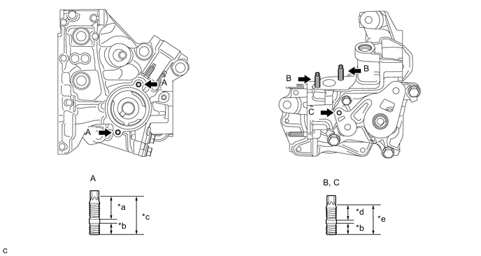
*a 21 mm (0.827 in.) *b 9.0 mm (0.354 in.) *c 34 mm (1.34 in.) *d 16 mm (0.630 in.) *e 27 mm (1.06 in.) - - - Torque:
- Stud Bolt (A), (B)
- 4.4 N*m { 45 kgf*cm, 39 in.*lbf }
- Stud Bolt (C)
- 4.0 N*m { 41 kgf*cm, 35 in.*lbf }
-
Install a new gasket to the cylinder block sub-assembly.
-
Install the water inlet housing to the cylinder block sub-assembly with the 4 bolts and nut.
- Torque:
- 43 N*m { 438 kgf*cm, 32 ft.*lbf }
-
-
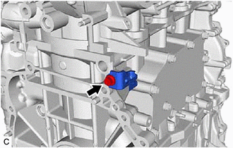
INSTALL ENGINE OIL TEMPERATURE SENSOR
-
INSTALL OIL COOLER ASSEMBLY
-
INSTALL THERMOSTAT
-
INSTALL WATER INLET
-
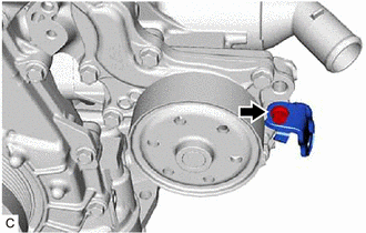
INSTALL ENGINE WATER PUMP ASSEMBLY
-
INSTALL WIRE HARNESS CLAMP BRACKET
-
Install the wire harness clamp bracket with the bolt.
- Torque:
- 21 N*m { 214 kgf*cm, 15 ft.*lbf }
-
Install the wire harness clamp bracket with the bolt.
- Torque:
- 10 N*m { 102 kgf*cm, 7 ft.*lbf }
-
-
INSTALL NO. 1 WATER BY-PASS PIPE
-
Install a new gasket and the No. 1 water by-pass pipe with the 2 nuts and bolt.
- Torque:
- 10 N*m { 102 kgf*cm, 7 ft.*lbf }
-
-
INSTALL V-RIBBED BELT TENSIONER ASSEMBLY
-
Install the V-ribbed belt tensioner assembly to the water inlet housing with the bolt.
- Torque:
- 21 N*m { 214 kgf*cm, 15 ft.*lbf }
-
Install the dust cover to the V-ribbed belt tensioner assembly.
-
-
INSTALL FUEL INJECTOR SEAL
-
INSTALL DIRECT FUEL INJECTOR ASSEMBLY
-
INSTALL FUEL DELIVERY PIPE WITH SENSOR ASSEMBLY
-
INSTALL NO. 5 ENGINE WIRE
-
Engage the 2 clamps and install the No. 5 engine wire.
-
Connect the fuel pressure sensor connector, knock control sensor connector and 4 fuel injector set connectors.
-
Connect the No. 5 engine wire to the fuel delivery pipe (for Direct Injection) with the 2 bolts.
- Torque:
- 10 N*m { 102 kgf*cm, 7 ft.*lbf }
-
-
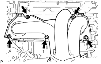
INSTALL INTAKE MANIFOLD
-
Install a new manifold gasket to the intake manifold.
-
Temporarily install the intake manifold to the cylinder head sub-assembly with the 6 bolts.
-
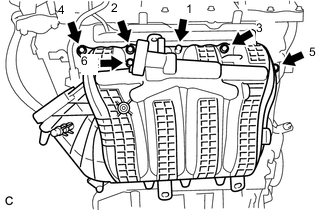
Tighten the 6 bolts in the order shown in the illustration.
- Torque:
- 28 N*m { 286 kgf*cm, 21 ft.*lbf }
-
-
CONNECT NO. 2 VENTILATION HOSE
-
INSTALL THROTTLE BODY GASKET
-
INSTALL THROTTLE BODY WITH MOTOR ASSEMBLY
-
INSTALL PORT FUEL INJECTOR ASSEMBLY
-
INSTALL INJECTOR VIBRATION INSULATOR
-
INSTALL FUEL DELIVERY SPACER
-
INSTALL FUEL DELIVERY PIPE
-
CONNECT FUEL TUBE SUB-ASSEMBLY (for Port Injection)
-
TEMPORARILY INSTALL FUEL PUMP WITH SEAL SUB-ASSEMBLY
-
TEMPORARILY INSTALL NO. 1 FUEL PIPE SUB-ASSEMBLY
-
INSTALL FUEL PUMP WITH SEAL SUB-ASSEMBLY
-
INSTALL NO. 1 FUEL PIPE SUB-ASSEMBLY
-
INSTALL NO. 1 FUEL PIPE
-
CONNECT NO. 2 FUEL TUBE SUB-ASSEMBLY (for Direct Injection)
-
INSTALL NO. 1 COMPRESSOR MOUNTING BRACKET
-
Install the No. 1 compressor mounting bracket with the 4 bolts.
- Torque:
- 21 N*m { 214 kgf*cm, 15 ft.*lbf }
-
-
INSTALL DRIVE SHAFT BEARING BRACKET
-
Install the drive shaft bearing bracket with the 3 bolts.
- Torque:
- 63.7 N*m { 650 kgf*cm, 47 ft.*lbf }
Note
Make sure that the bolts and bolt holes are free of oil. Clean them if necessary.
-
-
INSTALL COMPRESSOR ASSEMBLY WITH MAGNETIC CLUTCH
-
for Type A:
-
Using an E8 "TORX" socket wrench, temporarily install the compressor assembly with magnetic clutch with the 2 stud bolts.
- Torque:
- 10 N*m { 102 kgf*cm, 7 ft.*lbf }
-
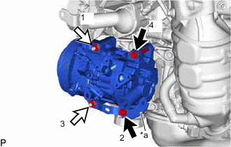
*a Bracket 
Bolt 
Nut Install the compressor assembly with magnetic clutch and bracket with the 2 bolts and 2 nuts.
- Torque:
- 24.5 N*m { 250 kgf*cm, 18 ft.*lbf }
Tech Tips
Tighten the bolts and nuts in the order shown in the illustration to install the compressor assembly with magnetic clutch.
-
-
for Type B:
-
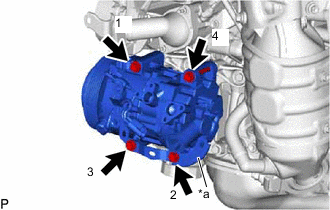
*a Bracket Install the compressor assembly with magnetic clutch and bracket with the 4 bolts.
- Torque:
- 24.5 N*m { 250 kgf*cm, 18 ft.*lbf }
Tech Tips
Tighten the bolts in the order shown in the illustration to install the compressor assembly with magnetic clutch.
-
-
-
INSTALL WIRE HARNESS CLAMP BRACKET
-
INSTALL WIRE HARNESS CLAMP BRACKET
-
Install the wire harness clamp bracket with the bolt.
- Torque:
- 10 N*m { 102 kgf*cm, 7 ft.*lbf }
-
Install the wire harness clamp bracket with the bolt.
- Torque:
- 10 N*m { 102 kgf*cm, 7 ft.*lbf }
-
Install the wire harness clamp bracket with the bolt.
- Torque:
- 10 N*m { 102 kgf*cm, 7 ft.*lbf }
-
Install the wire harness clamp bracket with the bolt.
- Torque:
- 10 N*m { 102 kgf*cm, 7 ft.*lbf }
-
-
INSTALL GENERATOR ASSEMBLY
-
INSTALL V-RIBBED BELT
-
INSTALL EXHAUST MANIFOLD CONVERTER SUB-ASSEMBLY (TWC: Front Catalyst)
-
Install a new exhaust manifold gasket to the cylinder head sub-assembly.
-
Temporarily install the exhaust manifold converter sub-assembly (TWC: Front Catalyst) to the cylinder head sub-assembly with the 5 nuts.
-
Tighten the 5 nuts in the order shown in the illustration.
- Torque:
- 62 N*m { 632 kgf*cm, 46 ft.*lbf }
-
-
INSTALL NO. 2 MANIFOLD STAY
-
INSTALL MANIFOLD STAY
-
INSTALL NO. 1 EXHAUST MANIFOLD HEAT INSULATOR
-
INSTALL EGR VALVE WITH COOLER ASSEMBLY
-
INSTALL FUEL PUMP PROTECTOR
-
INSTALL ENGINE OIL LEVEL DIPSTICK GUIDE
-
Apply a light coat of engine oil to a new O-ring.
-
Install the O-ring to the engine oil level dipstick guide.
-
Install the engine oil level dipstick guide with the bolt.
- Torque:
- 10 N*m { 102 kgf*cm, 7 ft.*lbf }
-
Install the engine oil level dipstick.
-