ВПУСКНОЙ КОЛЛЕКТОР СНЯТИЕ

Note
-
When replacing the parts in the following chart (A), replace the No. 1 injection pipe sub-assembly, No. 2 injection pipe sub-assembly and/or fuel inlet pipe sub-assembly with new ones.
Replaced Parts (A) Pipes Requiring New Replacement
-
Injector assembly (including shuffling the injector assemblies between the cylinders)
-
Common rail assembly
-
Injection pipe sub-assembly or supply pump assembly
-
No. 1 injection pipe sub-assembly
-
No. 2 injection pipe sub-assembly
Common rail assembly Fuel inlet pipe sub-assembly
-
Injection pipe sub-assembly or supply pump assembly
-
Cylinder block sub-assembly
-
Cylinder head sub-assembly
-
Cylinder head gasket
-
Timing chain case assembly or belt cover sub-assembly
-
No. 1 injection pipe sub-assembly
-
No. 2 injection pipe sub-assembly
-
Fuel inlet pipe sub-assembly
-
-
After removing the No. 1 injection pipe sub-assembly, No. 2 injection pipe sub-assembly and/or fuel inlet pipe sub-assembly, clean them with a brush and compressed air.
-
DISCONNECT CABLE FROM NEGATIVE BATTERY TERMINAL
Note
When disconnecting the cable, some systems need to be initialized after the cable is reconnected Click here.
-
REMOVE EGR COOLER ASSEMBLY
-
REMOVE ENGINE OIL LEVEL DIPSTICK GUIDE
-
w/ No. 2 Fuel Pipe Clamp:
Detach the No. 2 fuel pipe clamp from the engine oil level dipstick guide.
-
Remove the engine oil level dipstick.
-
Slide the clip and disconnect vacuum hose from the intake manifold.
-
Remove the bolt and engine oil level dipstick guide.
-
Remove the O-ring and grommet from the engine oil level dipstick guide.
-
-
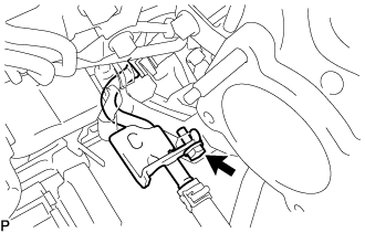
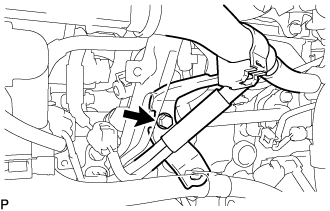
DISCONNECT NO. 2 FUEL PIPE
-
Remove the bolt and disconnect the No. 2 fuel pipe.
-
-
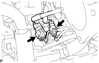
REMOVE WIRING HARNESS CLAMP BRACKET
-
Disconnect the diesel throttle body assembly connector and pre-stroke control valve connector.
-
Detach the 2 wire harness clamps.
-
Remove the bolt and wiring harness clamp bracket.
-
-
REMOVE MANIFOLD STAY
-
Remove the bolt and disconnect the wiring harness clamp bracket from the manifold stay.
-
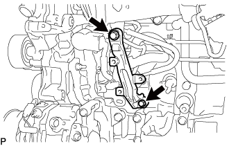
Remove the 2 bolts and manifold stay.
-
-
REMOVE NO. 4 FUEL PIPE SUB-ASSEMBLY
-
Disconnect the No. 4 fuel pipe sub-assembly from the No. 1 fuel pipe Click here.
Text in Illustration 
Union Bolt 
Bolt -
Remove the bolt from the intake manifold.
-
Remove the 2 union bolts and 2 gaskets from the supply pump assembly and fuel filter.
-
-
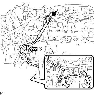
REMOVE NO. 3 FUEL PIPE
-
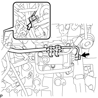
Remove the union bolts, supply pump hollow screw and 2 gaskets from the supply pump assembly and fuel filter.
Text in Illustration 
Union Bolt 
Supply Pump Hollow Screw -
Remove the 2 fuel pipe clamps from the No. 3 fuel pipe and fuel filter.
-
-
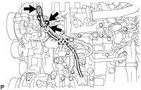
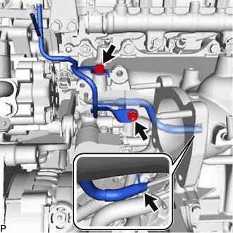
REMOVE FUEL INLET PIPE SUB-ASSEMBLY
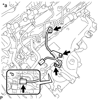
Text in Illustration *a Common Rail Assembly Side *b Fuel Supply Pump Assembly Side
-
Remove the 2 bolts, No. 1 injection pipe clamp and No. 2 injection pipe clamp.
-
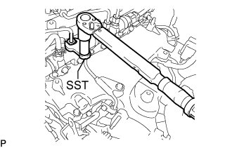
Using SST, loosen the fuel inlet pipe sub-assembly union nut of the common rail assembly side.
- SST
- 09245-11010
Note
If the No. 1 or No. 2 injection pipe clamp is removed from the inlet pipe sub-assembly, replace the No. 1 or No. 2 injection clamp with a new one.
-
Using a 19 mm union nut wrench, loosen the inlet pipe sub-assembly union nut of the fuel supply pump assembly side.
-
-
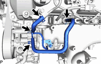
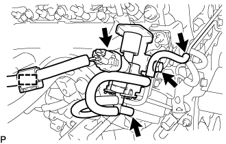
REMOVE NO. 2 NOZZLE LEAKAGE PIPE ASSEMBLY
-
Slide the 2 clamps and remove the No. 4 fuel hose from the No. 2 nozzle leakage pipe assembly and common rail assembly.
-
Slide the 2 clamps and remove the No. 5 fuel hose from the No. 1 nozzle leakage pipe assembly and No. 2 nozzle leakage pipe assembly.
-
Slide the clamp and disconnect the No. 6 fuel hose from the No. 3 nozzle leakage pipe assembly.
-
Remove the 2 bolts and No. 2 nozzle leakage pipe assembly.
-
-
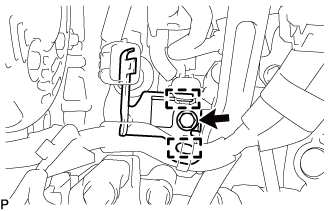
REMOVE VACUUM CONTROL VALVE SET
-
Disconnect the wire harness clamp and vacuum control valve set connector.
-
Disconnect the 2 vacuum hoses from the swirl control valve actuator and vacuum transmitting pipe sub-assembly.
-
Remove the bolt and vacuum control valve set from the intake manifold.
-
-
REMOVE INTAKE MANIFOLD
-
Remove the bolt and disconnect the wire harness bracket.
-
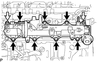
Remove the 7 bolts, 2 nuts, intake manifold and gasket.
Text in Illustration 
Bolt Nut
-