AIR CONDITIONING SYSTEM(for Manual Air Conditioning System) Blower Motor Circuit
| DTC Code | DTC Name |
|---|---|
| Blower Motor Circuit |
DESCRIPTION
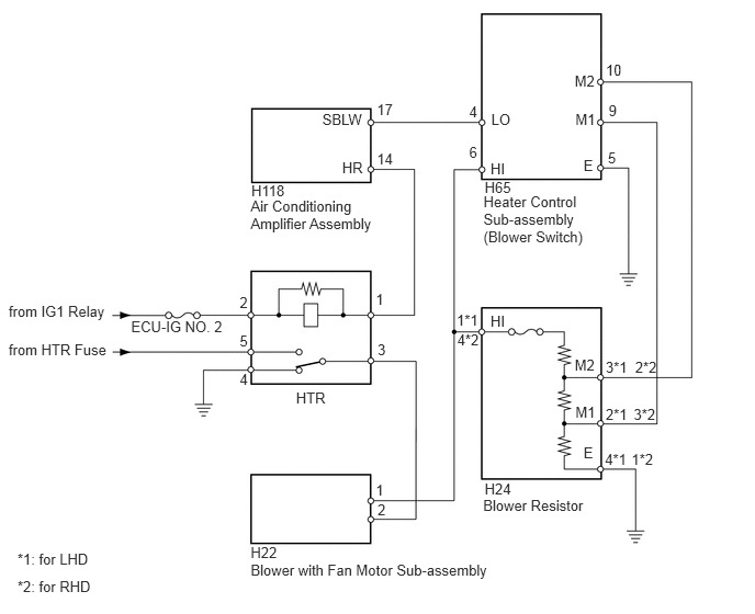
When the heater control sub-assembly (blower switch) is operated, the HTR relay will turn on to allow current to flow to the blower with fan motor sub-assembly and then the motor will start rotating. Operating the heater control sub-assembly (blower switch) changes the current flow between the blower resistor and body ground, which changes the rotation speed of the blower with fan motor sub-assembly.
WIRING DIAGRAM
CAUTION / NOTICE / HINT
Inspect the fuses for circuits related to this system before performing the following inspection procedure.
PROCEDURE
INSPECT RELAY (HTR)
-
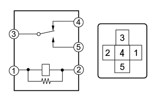
Remove the HTR relay from the instrument panel junction block.
Measure the resistance according to the value(s) in the table below.
Standard Resistance
Tester Connection
Condition
Specified Condition
3 - 4
Battery voltage is not applied to terminals 1 and 2
Below 1 Ω
3 - 4
Battery voltage is applied to terminals 1 and 2
10 kΩ or higher
3 - 5
Battery voltage is not applied to terminals 1 and 2
10 kΩ or higher
3 - 5
Battery voltage is applied to terminals 1 and 2
Below 1 Ω
REPLACE RELAY (HTR)
-
INSPECT BLOWER WITH FAN MOTOR SUB-ASSEMBLY
-
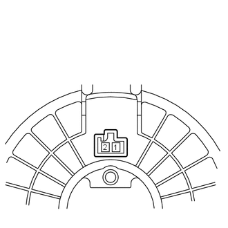
Remove the blower with fan motor sub-assembly (Click here).
Apply battery voltage to the blower with fan motor sub-assembly and check the operation of the blower with fan motor sub-assembly.
OK
Measurement Condition
Specified Condition
Battery positive (+) → Terminal 2
Battery negative (-) → Terminal 1
Blower with fan motor sub-assembly operation is normal
-
INSPECT BLOWER RESISTOR
-
Remove the blower resistor (Click here).
Measure the resistance according to the value(s) in the table below.
Standard Resistance
Table 1. for LHD Tester Connection
Condition
Specified Condition
1 (HI) - 4 (E)
Always
3.12 to 3.60 Ω
3 (M2) - 1 (HI)
Always
0.52 to 0.60 Ω
2 (M1) - 1 (HI)
Always
1.45 to 1.67 Ω
Table 2. for RHD Tester Connection
Condition
Specified Condition
4 (HI) - 1 (E)
Always
3.12 to 3.60 Ω
2 (M2) - 4 (HI)
Always
0.52 to 0.60 Ω
3 (M1) - 4 (HI)
Always
1.45 to 1.67 Ω
Table 3. Text in Illustration *1
for LHD
*2
for RHD
-
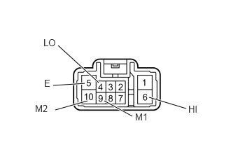
INSPECT HEATER CONTROL SUB-ASSEMBLY (BLOWER SWITCH)
-
Remove the heater control sub-assembly (blower switch) (Click here).
Measure the resistance according to the value(s) in the table below.
Standard Resistance
Tester Connection
Switch Condition
Specified Condition
4 (LO), 6 (HI), 9 (M1) or 10 (M2) - 5 (E)
Blower switch OFF
10 kΩ or higher
4 (LO) - 5 (E)
Blower switch LO
Below 1 Ω
4 (LO) or 9 (M1) - 5 (E)
Blower switch M1
Below 1 Ω
4 (LO) or 10 (M2) - 5 (E)
Blower switch M2
Below 1 Ω
4 (LO) or 6 (HI) - 5 (E)
Blower switch HI
Below 1 Ω
-
CHECK HARNESS AND CONNECTOR (AIR CONDITIONING AMPLIFIER ASSEMBLY - BATTERY)
-
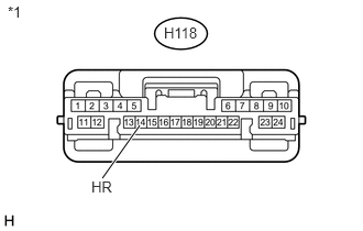
Disconnect the H118 amplifier connector.
Measure the voltage according to the value(s) in the table below.
Standard Voltage
Tester Connection
Switch Condition
Specified Condition
H118-14 (HR) - Body ground
Ignition switch ON
Blower switch LO
Below 1 V
H118-14 (HR) - Body ground
Ignition switch ON
Blower switch OFF
11 to 14 V
Table 4. Text in Illustration *1
Front view of wire harness connector
(to Air Conditioning Amplifier Assembly)
REPAIR OR REPLACE HARNESS OR CONNECTOR
-
CHECK HARNESS AND CONNECTOR (HEATER CONTROL [BLOWER SWITCH] - BATTERY)
-
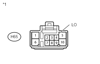
Disconnect the H65 heater control connector.
Measure the voltage according to the value(s) in the table below.
Standard Voltage
Tester Connection
Switch Condition
Specified Condition
H65-4 (LO) - Body ground
Ignition switch ON
11 to 14 V
H65-4 (LO) - Body ground
Ignition switch off
Below 1 V
Table 5. Text in Illustration *1
Front view of wire harness connector
(to Heater Control Sub-assembly [Blower Switch])
REPAIR OR REPLACE HARNESS OR CONNECTOR
-
CHECK HARNESS AND CONNECTOR (BLOWER RESISTOR - HEATER CONTROL [BLOWER SWITCH])
-
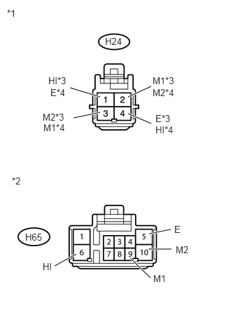
Disconnect the H24 resistor connector.
Disconnect the H65 heater control connector.
Measure the resistance according to the value(s) in the table below.
Standard Resistance
Table 6. for LHD Tester Connection
Condition
Specified Condition
H24-1 (HI) - H65-6 (HI)
Always
Below 1 Ω
H24-3 (M2) - H65-10 (M2)
Always
Below 1 Ω
H24-2 (M1) - H65-9 (M1)
Always
Below 1 Ω
H24-4 (E) - Body ground
Always
Below 1 Ω
H65-5 (E) - Body ground
Always
Below 1 Ω
H24-1 (HI) - Body ground
Always
10 kΩ or higher
H24-3 (M2) - Body ground
Always
10 kΩ or higher
H24-2 (M1) - Body ground
Always
10 kΩ or higher
Table 7. for RHD Tester Connection
Condition
Specified Condition
H24-4 (HI) - H65-6 (HI)
Always
Below 1 Ω
H24-2 (M2) - H65-10 (M2)
Always
Below 1 Ω
H24-3 (M1) - H65-9 (M1)
Always
Below 1 Ω
H24-1 (E) - Body ground
Always
Below 1 Ω
H65-5 (E) - Body ground
Always
Below 1 Ω
H24-4 (HI) - Body ground
Always
10 kΩ or higher
H24-2 (M2) - Body ground
Always
10 kΩ or higher
H24-3 (M1) - Body ground
Always
10 kΩ or higher
Table 8. Text in Illustration *1
Front view of wire harness connector
(to Blower Resistor)
*2
Front view of wire harness connector
(to Heater Control Sub-assembly [Blower Switch])
*3
for LHD
*4
for RHD
REPAIR OR REPLACE HARNESS OR CONNECTOR
-
CHECK HARNESS AND CONNECTOR (BLOWER WITH FAN MOTOR - BLOWER RESISTOR AND HEATER CONTROL [BLOWER SWITCH])
Disconnect the H22 blower connector.
Disconnect the H24 resistor connector.
Disconnect the H65 heater control connector.
Measure the resistance according to the value(s) in the table below.
Standard Resistance
Table 9. for LHD Tester Connection
Condition
Specified Condition
H22-1 - H24-1 (HI)
Always
Below 1 Ω
H22-1 - H65-6 (HI)
Always
Below 1 Ω
H22-1 - Body ground
Always
10 kΩ or higher
Table 10. for RHD Tester Connection
Condition
Specified Condition
H22-1 - H24-4 (HI)
Always
Below 1 Ω
H22-1 - H65-6 (HI)
Always
Below 1 Ω
H22-1 - Body ground
Always
10 kΩ or higher
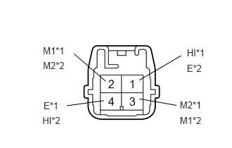
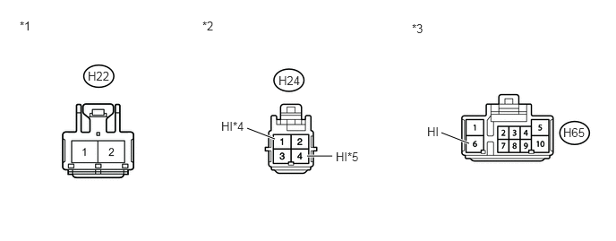
Table 11. Text in Illustration *1
Front view of wire harness connector
(to Blower with Fan Motor Sub-assembly)
*2
Front view of wire harness connector
(to Blower Resistor)
*3
Front view of wire harness connector
(to Heater Control Sub-assembly [Blower Switch])
*4
for LHD
*5
for RHD
REPAIR OR REPLACE HARNESS OR CONNECTOR
CHECK HARNESS AND CONNECTOR (BLOWER WITH FAN MOTOR - BATTERY)
-
Disconnect the H22 blower connector.
Measure the voltage according to the value(s) in the table below.
Standard Voltage
Tester Connection
Switch Condition
Specified Condition
H22-2 - Body ground
Ignition switch ON
Blower switch off
Below 1 V
H22-2 - Body ground
Ignition switch ON
Blower switch on
11 to 14 V
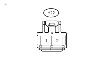
Table 12. Text in Illustration *1
Front view of wire harness connector
(to Blower with Fan Motor Sub-assembly)
END
REPAIR OR REPLACE HARNESS OR CONNECTOR
-