CAN COMMUNICATION SYSTEM(for LHD with Central Gateway ECU) TERMINALS OF ECU
Operating the ignition switch, any switches or any doors triggers related ECU and sensor communication with the CAN, which causes resistance variation.
DISCONNECT CABLE FROM NEGATIVE BATTERY TERMINAL
Disconnect the cable from the negative (-) battery terminal before measuring the resistances of the CAN main wire and the CAN branch wire.
CAUTION:Wait at least 90 seconds after disconnecting the cable from the negative (-) battery terminal to disable the airbag system.
Note:Before measuring the resistance, leave the vehicle for at least 1 minute and do not operate the ignition switch, any switches or any doors. If doors need to be opened in order to check connectors, open the doors and leave them open.
After turning the cable disconnected from negative (-) battery terminal, waiting time may be required before disconnecting the cable from the battery terminal. Therefore, make sure to read the disconnecting the cable from the battery terminal notice before proceeding with work.
When disconnecting the cable, some systems need to be initialized after the cable is reconnected.
JUNCTION CONNECTOR
No. 4 CAN Junction Connector (w/ Seat Memory)
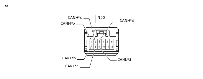
*a
Front view of wire harness connector
(to No. 4 CAN Junction Connector)
*b
for Main Body ECU (Multiplex Network Body ECU)
*c
for No. 5 CAN Junction Connector
*d
for Position Control ECU and Switch Assembly
No. 4 CAN Junction Connector
Wiring Color
Connect to
N30-1 (CANH)
B
Main body ECU (multiplex network body ECU)
N30-7 (CANL)
GR
N30-2 (CANH)
V
No. 5 CAN junction connector
N30-8 (CANL)
GR
N30-3 (CANH)
R
Position control ECU and switch assembly
N30-9 (CANL)
GR
No. 5 CAN Junction Connector (w/ Power Back Door System)
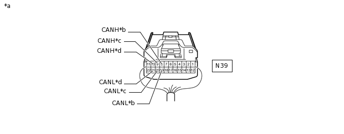
*a
Rear view of wire harness connector
(to No. 5 CAN Junction Connector)
*b
for Main Body ECU (Multiplex Network Body ECU) (w/o Seat Memory)
for No. 4 CAN Junction Connector (w/ Seat Memory)
*c
for Multiplex Network Door ECU
*d
for No. 1 CAN Junction Terminal
No. 5 CAN Junction Connector
Wiring Color
Connect to
N39-8 (CANH)
B*1
V*2
Main body ECU (multiplex network body ECU)*1
No. 4 CAN junction connector*2
N39-19 (CANL)
GR
N39-9 (CANH)
G
Multiplex network door ECU
N39-20 (CANL)
GR
N39-10 (CANH)
L
No. 1 CAN junction terminal
N39-21 (CANL)
GR
*1: w/o Seat Memory
*2: w/ Seat Memory
No. 6 CAN Junction Connector
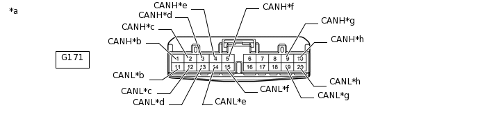
*a
Front view of wire harness connector
(to No. 6 CAN Junction Connector)
*b
for Main Body ECU (Multiplex Network Body ECU)
*c
for Power Steering ECU Assembly
*d
for Brake Actuator Assembly (Skid Control ECU)
*e
for No. 7 CAN Junction Connector
*f
for ECM
*g
for Airbag Sensor Assembly
*h
for Air Conditioning Amplifier Assembly
No. 6 CAN Junction Connector
Wiring Color
Connect to
G171-1 (CANH)
G
Main body ECU (multiplex network body ECU)
G171-11 (CANL)
W
G171-2 (CANH)
BE
Power steering ECU assembly
G171-12 (CANL)
W
G171-3 (CANH)
GR
Brake actuator assembly (skid control ECU)
G171-13 (CANL)
W
G171-4 (CANH)
V
No. 7 CAN junction connector
G171-14 (CANL)
W
G171-5 (CANH)
Y
ECM
G171-15 (CANL)
W
G171-9 (CANH)
BR
Airbag sensor assembly
G171-19 (CANL)
W
G171-10 (CANH)
B
Air conditioning amplifier assembly
G171-20 (CANL)
W
No. 7 CAN Junction Connector
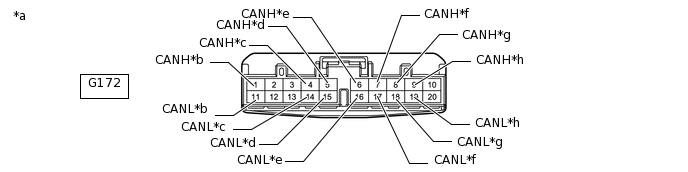
*a
Front view of wire harness connector
(to No. 7 CAN Junction Connector)
*b
for Combination Meter Assembly
*c
for Engine Stop and Start ECU (w/ Stop and Start System)
*d
for Certification ECU (Smart Key ECU Assembly) (w/ Entry and Start System)
*e
for 4WD ECU Assembly (for 4WD/AWD)
*f
for Central Gateway ECU
*g
for No. 6 CAN Junction Connector
*h
for Spiral with Sensor Cable Sub-assembly (Steering Angle Sensor)
No. 7 CAN Junction Connector
Wiring Color
Connect to
G172-1 (CANH)
G
Combination meter assembly
G172-11 (CANL)
W
G172-4 (CANH)
LG
Engine stop and start ECU*3
G172-14 (CANL)
W
G172-5 (CANH)
R
Certification ECU (smart key ECU assembly)*1
G172-15 (CANL)
W
G172-6 (CANH)
GR
4WD ECU assembly*2
G172-16 (CANL)
W
G172-7 (CANH)
SB
Central gateway ECU
G172-17 (CANL)
W
G172-8 (CANH)
V
No. 6 CAN junction connector
G172-18 (CANL)
W
G172-9 (CANH)
P
Spiral with sensor cable sub-assembly (steering angle sensor)
G172-19 (CANL)
W
*1: w/ Entry and Start System
*2: for 4WD/AWD
*3: w/ Stop and Start System
No. 8 CAN Junction Connector
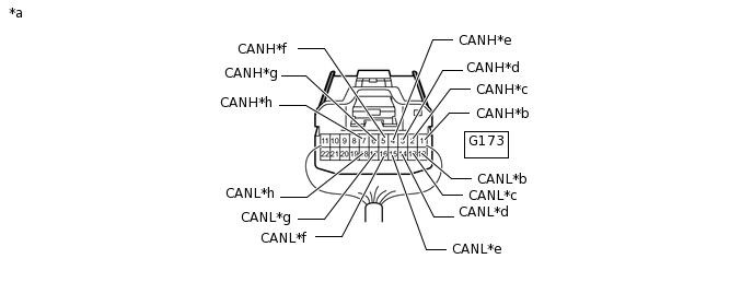
*a
Rear view of wire harness connector
(to No. 8 CAN Junction Connector)
*b
for Radio and Display Receiver Assembly (w/ Audio and Visual System [for Radio and Display Type])
*c
for No. 13 CAN Junction Connector (w/ Telematics Transceiver)
*d
for Central Gateway ECU
*e
for Central Gateway ECU (w/o Telematics Transceiver)
*f
for Driving Support ECU Assembly (w/ Pre-crash Safety System)
*g
for Forward Recognition Camera (w/ Pre-crash Safety System)
*h
for Millimeter Wave Radar Sensor Assembly (w/ Pre-crash Safety System)
No. 8 CAN Junction Connector
Wiring Color
Connect to
G173-1 (CANH)
Y
Radio and display receiver assembly*1
G173-12 (CANL)
W
G173-2 (CANH)
L
No. 13 CAN junction connector*3
G173-13 (CANL)
W
G173-3 (CANH)
R
Central gateway ECU
G173-14 (CANL)
W
G173-4 (CANH)
V
Central gateway ECU*4
G173-15 (CANL)
W
G173-5 (CANH)
B
Driving support ECU assembly*2
G173-16 (CANL)
W
G173-6 (CANH)
L
Forward recognition camera*2
G173-17 (CANL)
W
G173-7 (CANH)
SB
Millimeter wave radar sensor assembly*2
G173-18 (CANL)
W
*1: w/ Audio and Visual System (for Radio and Display Type)
*2: w/ Pre-crash Safety System
*3: w/ Telematics Transceiver
*4: w/o Telematics Transceiver
No. 9 CAN Junction Connector
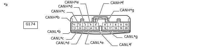
*a
Front view of wire harness connector
(to No. 9 CAN Junction Connector)
*b
for Forward Recognition Camera (w/ Pre-crash Safety System)
*c
for Millimeter Wave Radar Sensor Assembly (w/ Pre-crash Safety System)
*d
for Driving Support ECU Assembly (w/ Pre-crash Safety System)
*e
for Central Gateway ECU
*f
for No. 10 CAN Junction Connector
*g
for Clearance Warning ECU Assembly (w/ TOYOTA Parking Assist-sensor System [for 8 Sensor Type])
-
-
No. 9 CAN Junction Connector
Wiring Color
Connect to
G174-1 (CANH)
G
Forward recognition camera*1
G174-11 (CANL)
LG
G174-2 (CANH)
B
Millimeter wave radar sensor assembly*1
G174-12 (CANL)
LG
G174-3 (CANH)
P
Driving support ECU assembly*1
G174-13 (CANL)
LG
G174-4 (CANH)
Y
Central gateway ECU
G174-14 (CANL)
LG
G174-5 (CANH)
L
No. 10 CAN junction connector
G174-15 (CANL)
LG
G174-6 (CANH)
R
Clearance warning ECU assembly*2
G174-16 (CANL)
LG
*1: w/ Pre-crash Safety System
*2: w/ TOYOTA Parking Assist-sensor System (for 8 Sensor Type)
No. 10 CAN Junction Connector
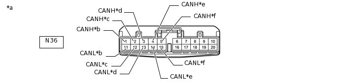
*a
Front view of wire harness connector
(to No. 10 CAN Junction Connector)
*b
for Parking Assist ECU (w/ Panoramic View Monitor System)
*c
for Central Gateway ECU
*d
for No. 9 CAN Junction Connector
*e
for Blind Spot Monitor Sensor LH (w/ Blind Spot Monitor System)
*f
for Television Camera Assembly (w/ Parking Assist Monitor System [for Camera built-in ECU])
No. 10 CAN Junction Connector
Wiring Color
Connect to
N36-1 (CANH)
G
Parking assist ECU*1
N36-11 (CANL)
LG
N36-2 (CANH)
V
Central gateway ECU
N36-12 (CANL)
LG
N36-3 (CANH)
L
No. 9 CAN junction connector
N36-13 (CANL)
LG
N36-4 (CANH)
R
Blind spot monitor sensor LH*2
N36-14 (CANL)
LG
N36-5 (CANH)
P
Television camera assembly*3
N36-15 (CANL)
LG
*1: w/ Panoramic View Monitor System
*2: w/ Blind Spot Monitor System
*3: w/ Parking Assist Monitor System (for Camera built-in ECU)
No. 13 CAN Junction Connector (w/ Telematics Transceiver)
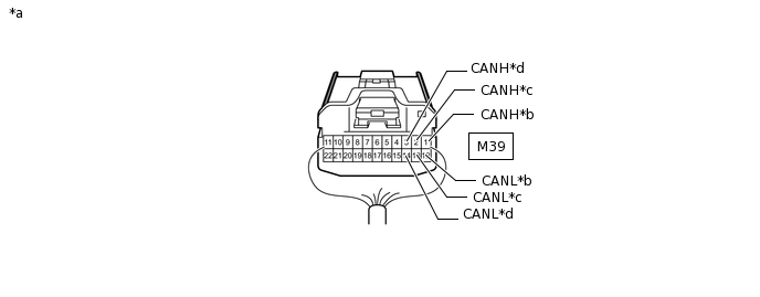
*a
Rear view of wire harness connector
(to No. 13 CAN Junction Connector)
*b
for Telematics Transceiver
*c
for Central Gateway ECU
*d
for No. 8 CAN Junction Connector
No. 13 CAN Junction Connector
Wiring Color
Connect to
M39-1 (CANH)
R
Telematics transceiver
M39-12 (CANL)
W
M39-2 (CANH)
V
Central gateway ECU
M39-13 (CANL)
W
M39-3 (CANH)
L
No. 8 CAN junction connector
M39-14 (CANL)
W
-
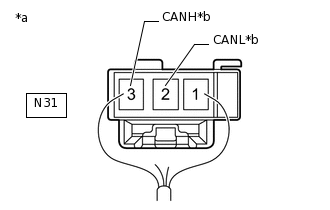
*a
Rear view of wire harness connector
(to No. 1 CAN Junction Terminal)
*b
for No. 5 CAN Junction Connector
No. 1 CAN Junction Terminal (w/ Power Back Door System)
No. 1 CAN Junction Terminal
Wiring Color
Connect to
N31-2 (CANL)
GR
No. 5 CAN junction connector
N31-3 (CANH)
L
CHECK DLC3
-
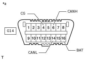
*a
Front view of DLC3
Disconnect the cable from the negative (-) battery terminal before measuring the resistances of the CAN main wire and the CAN branch wire.
CAUTION:Wait at least 90 seconds after disconnecting the cable from the negative (-) battery terminal to disable the airbag system.
Note:After turning the cable disconnected from negative (-) battery terminal, waiting time may be required before disconnecting the cable from the battery terminal. Therefore, make sure to read the disconnecting the cable from the battery terminal notice before proceeding with work.
When disconnecting the cable, some systems need to be initialized after the cable is reconnected.
Measure the resistance according to the value(s) in the table below.
Terminal No. (Symbol)
Wiring Color
Terminal Description
Condition
Specified Condition
G14-6 (CANH) - G14-14 (CANL)
B - W
HIGH-level CAN bus wire - LOW-level CAN bus wire
Cable disconnected from negative (-) battery terminal
54 to 66 Ω
G14-6 (CANH) - G14-4 (CG)
B - BR
HIGH-level CAN bus wire - GND
Cable disconnected from negative (-) battery terminal
200 Ω or higher
G14-14 (CANL) - G14-4 (CG)
W - BR
LOW-level CAN bus wire - GND
Cable disconnected from negative (-) battery terminal
200 Ω or higher
G14-6 (CANH) - G14-16 (BAT)
B - L
HIGH-level CAN bus wire - Battery positive (+)
Cable disconnected from negative (-) battery terminal
6 kΩ or higher
G14-14 (CANL) - G14-16 (BAT)
W - L
LOW-level CAN bus wire - Battery positive (+)
Cable disconnected from negative (-) battery terminal
6 kΩ or higher
-
CHECK CENTRAL GATEWAY ECU
*A
Bus 2
*B
Bus 3
*C
Bus 5
*D
V Bus
-
*A
Bus 2
*B
Bus 3
*C
Bus 5
*D
V Bus
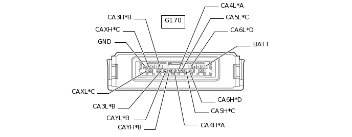
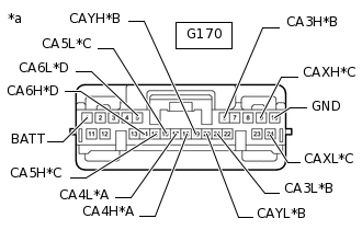
*a
Front view of wire harness connector
(to Central Gateway ECU)
Disconnect the central gateway ECU connector.
Measure the resistance according to the value(s) in the table below.
Table 1. Bus 2 Terminal No. (Symbol)
Wiring Color
Terminal Description
Condition
Specified Condition
G170-18 (CA4H) - G170-17 (CA4L)
SB - W
HIGH-level CAN bus wire - LOW-level CAN bus wire
Cable disconnected from negative (-) battery terminal
54 to 69 Ω
G170-18 (CA4H) - G170-10 (GND)
SB - W-B
HIGH-level CAN bus wire - GND
Cable disconnected from negative (-) battery terminal
200 Ω or higher
G170-17 (CA4L) - G170-10 (GND)
W - W-B
LOW-level CAN bus wire - GND
Cable disconnected from negative (-) battery terminal
200 Ω or higher
G170-18 (CA4H) - G170-1 (BATT)
SB - GR
HIGH-level CAN bus wire - Battery positive (+)
Cable disconnected from negative (-) battery terminal
6 kΩ or higher
G170-17 (CA4L) - G170-1 (BATT)
W - GR
LOW-level CAN bus wire - Battery positive (+)
Cable disconnected from negative (-) battery terminal
6 kΩ or higher
Table 2. Bus 3 Terminal No. (Symbol)
Wiring Color
Terminal Description
Condition
Specified Condition
G170-6 (CA3H) - G170-21 (CA3L)
R - W
HIGH-level CAN bus wire - LOW-level CAN bus wire
Cable disconnected from negative (-) battery terminal
200 Ω or higher
G170-6 (CA3H) - G170-10 (GND)
R - W-B
HIGH-level CAN bus wire - GND
Cable disconnected from negative (-) battery terminal
200 Ω or higher
G170-21 (CA3L) - G170-10 (GND)
W - W-B
LOW-level CAN bus wire - GND
Cable disconnected from negative (-) battery terminal
200 Ω or higher
G170-6 (CA3H) - G170-1 (BATT)
R - GR
HIGH-level CAN bus wire - Battery positive (+)
Cable disconnected from negative (-) battery terminal
6 kΩ or higher
G170-21 (CA3L) - G170-1 (BATT)
W - GR
LOW-level CAN bus wire - Battery positive (+)
Cable disconnected from negative (-) battery terminal
6 kΩ or higher
Table 3. Bus 3 Terminal No. (Symbol)
Wiring Color
Terminal Description
Condition
Specified Condition
G170-19 (CAYH) - G170-20 (CAYL)
V - W
HIGH-level CAN bus wire - LOW-level CAN bus wire
Cable disconnected from negative (-) battery terminal
200 Ω or higher
G170-19 (CAYH) - G170-10 (GND)
V - W-B
HIGH-level CAN bus wire - GND
Cable disconnected from negative (-) battery terminal
200 Ω or higher
G170-20 (CAYL) - G170-10 (GND)
W - W-B
LOW-level CAN bus wire - GND
Cable disconnected from negative (-) battery terminal
200 Ω or higher
G170-19 (CAYH) - G170-1 (BATT)
V - GR
HIGH-level CAN bus wire - Battery positive (+)
Cable disconnected from negative (-) battery terminal
6 kΩ or higher
G170-20 (CAYL) - G170-1 (BATT)
W - GR
LOW-level CAN bus wire - Battery positive (+)
Cable disconnected from negative (-) battery terminal
6 kΩ or higher
Table 4. Bus 5 Terminal No. (Symbol)
Wiring Color
Terminal Description
Condition
Specified Condition
G170-15 (CA5H) - G170-16 (CA5L)
Y - LG
HIGH-level CAN bus wire - LOW-level CAN bus wire
Cable disconnected from negative (-) battery terminal
200 Ω or higher
G170-15 (CA5H) - G170-10 (GND)
Y - W-B
HIGH-level CAN bus wire - GND
Cable disconnected from negative (-) battery terminal
200 Ω or higher
G170-16 (CA5L) - G170-10 (GND)
LG - W-B
LOW-level CAN bus wire - GND
Cable disconnected from negative (-) battery terminal
200 Ω or higher
G170-15 (CA5H) - G170-1 (BATT)
Y - GR
HIGH-level CAN bus wire - Battery positive (+)
Cable disconnected from negative (-) battery terminal
6 kΩ or higher
G170-16 (CA5L) - G170-1 (BATT)
LG - GR
LOW-level CAN bus wire - Battery positive (+)
Cable disconnected from negative (-) battery terminal
6 kΩ or higher
Table 5. Bus 5 Terminal No. (Symbol)
Wiring Color
Terminal Description
Condition
Specified Condition
G170-9 (CAXH) - G170-24 (CAXL)
V - LG
HIGH-level CAN bus wire - LOW-level CAN bus wire
Cable disconnected from negative (-) battery terminal
200 Ω or higher
G170-9 (CAXH) - G170-10 (GND)
V - W-B
HIGH-level CAN bus wire - GND
Cable disconnected from negative (-) battery terminal
200 Ω or higher
G170-24 (CAXL) - G170-10 (GND)
LG - W-B
LOW-level CAN bus wire - GND
Cable disconnected from negative (-) battery terminal
200 Ω or higher
G170-9 (CAXH) - G170-1 (BATT)
V - GR
HIGH-level CAN bus wire - Battery positive (+)
Cable disconnected from negative (-) battery terminal
6 kΩ or higher
G170-24 (CAXL) - G170-1 (BATT)
LG - GR
LOW-level CAN bus wire - Battery positive (+)
Cable disconnected from negative (-) battery terminal
6 kΩ or higher
Table 6. V Bus Terminal No. (Symbol)
Wiring Color
Terminal Description
Condition
Specified Condition
G170-14 (CA6H) - G170-10 (GND)
B - W-B
HIGH-level CAN bus wire - GND
Cable disconnected from negative (-) battery terminal
200 Ω or higher
G170-5 (CA6L) - G170-10 (GND)
W - W-B
LOW-level CAN bus wire - GND
Cable disconnected from negative (-) battery terminal
200 Ω or higher
G170-14 (CA6H) - G170-1 (BATT)
B - GR
HIGH-level CAN bus wire - Battery positive (+)
Cable disconnected from negative (-) battery terminal
6 kΩ or higher
G170-5 (CA6L) - G170-1 (BATT)
W - GR
LOW-level CAN bus wire - Battery positive (+)
Cable disconnected from negative (-) battery terminal
6 kΩ or higher
-
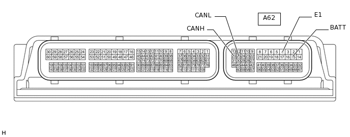
CHECK ECM
for 2AR-FE:
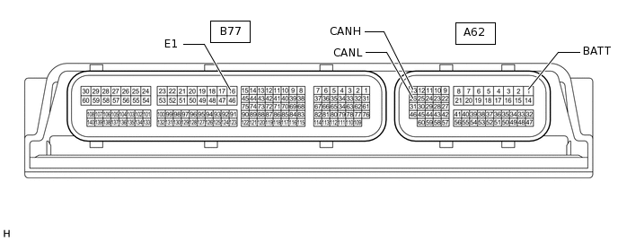
Disconnect the ECM connectors.
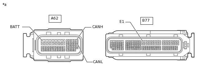
*a
Front view of wire harness connector
(to ECM)
-
-
Measure the resistance according to the value(s) in the table below.
Terminal No. (Symbol)
Wiring Color
Terminal Description
Condition
Specified Condition
A62-13 (CANH) - A62-26 (CANL)
Y - W
HIGH-level CAN bus wire - LOW-level CAN bus wire
Cable disconnected from negative (-) battery terminal
108 to 132 Ω
A62-13 (CANH) - B77-16 (E1)
Y - BR
HIGH-level CAN bus wire - GND
Cable disconnected from negative (-) battery terminal
200 Ω or higher
A62-26 (CANL) - B77-16 (E1)
W - BR
LOW-level CAN bus wire - GND
Cable disconnected from negative (-) battery terminal
200 Ω or higher
A62-13 (CANH) - A62-1 (BATT)
Y - W
HIGH-level CAN bus wire - Battery positive (+)
Cable disconnected from negative (-) battery terminal
6 kΩ or higher
A62-26 (CANL) - A62-1 (BATT)
W - W
LOW-level CAN bus wire - Battery positive (+)
Cable disconnected from negative (-) battery terminal
6 kΩ or higher
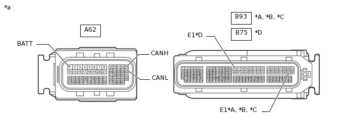
for 3ZR-FAE, 3ZR-FE:
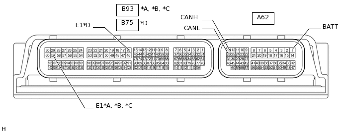
*A
for 3ZR-FAE
*B
for 3ZR-FE, Manual Transaxle System
*C
for 3ZR-FE, CVT (K114)
*D
for 3ZR-FE, CVT (K111)
Disconnect the ECM connectors.
*A
for 3ZR-FAE
*B
for 3ZR-FE, Manual Transaxle System
*C
for 3ZR-FE, CVT (K114)
*D
for 3ZR-FE, CVT (K111)
*a
Front view of wire harness connector
(to ECM)
-
-
Measure the resistance according to the value(s) in the table below.
Table 7. for 3ZR-FAE Terminal No. (Symbol)
Wiring Color
Terminal Description
Condition
Specified Condition
A62-13 (CANH) - A62-26 (CANL)
Y - W
HIGH-level CAN bus wire - LOW-level CAN bus wire
Cable disconnected from negative (-) battery terminal
108 to 132 Ω
A62-13 (CANH) - B93-59 (E1)
Y - BR
HIGH-level CAN bus wire - GND
Cable disconnected from negative (-) battery terminal
200 Ω or higher
A62-26 (CANL) - B93-59 (E1)
W - BR
LOW-level CAN bus wire - GND
Cable disconnected from negative (-) battery terminal
200 Ω or higher
A62-13 (CANH) - A62-1 (BATT)
Y - W
HIGH-level CAN bus wire - Battery positive (+)
Cable disconnected from negative (-) battery terminal
6 kΩ or higher
A62-26 (CANL) - A62-1 (BATT)
W - W
LOW-level CAN bus wire - Battery positive (+)
Cable disconnected from negative (-) battery terminal
6 kΩ or higher
Table 8. for 3ZR-FE, Manual Transaxle System Terminal No. (Symbol)
Wiring Color
Terminal Description
Condition
Specified Condition
A62-13 (CANH) - A62-26 (CANL)
Y - W
HIGH-level CAN bus wire - LOW-level CAN bus wire
Cable disconnected from negative (-) battery terminal
108 to 132 Ω
A62-13 (CANH) - B93-59 (E1)
Y - BR
HIGH-level CAN bus wire - GND
Cable disconnected from negative (-) battery terminal
200 Ω or higher
A62-26 (CANL) - B93-59 (E1)
W - BR
LOW-level CAN bus wire - GND
Cable disconnected from negative (-) battery terminal
200 Ω or higher
A62-13 (CANH) - A62-1 (BATT)
Y - W
HIGH-level CAN bus wire - Battery positive (+)
Cable disconnected from negative (-) battery terminal
6 kΩ or higher
A62-26 (CANL) - A62-1 (BATT)
W - W
LOW-level CAN bus wire - Battery positive (+)
Cable disconnected from negative (-) battery terminal
6 kΩ or higher
Table 9. for 3ZR-FE, CVT (K114) Terminal No. (Symbol)
Wiring Color
Terminal Description
Condition
Specified Condition
A62-13 (CANH) - A62-26 (CANL)
Y - W
HIGH-level CAN bus wire - LOW-level CAN bus wire
Cable disconnected from negative (-) battery terminal
108 to 132 Ω
A62-13 (CANH) - B93-59 (E1)
Y - BR
HIGH-level CAN bus wire - GND
Cable disconnected from negative (-) battery terminal
200 Ω or higher
A62-26 (CANL) - B93-59 (E1)
W - BR
LOW-level CAN bus wire - GND
Cable disconnected from negative (-) battery terminal
200 Ω or higher
A62-13 (CANH) - A62-1 (BATT)
Y - W
HIGH-level CAN bus wire - Battery positive (+)
Cable disconnected from negative (-) battery terminal
6 kΩ or higher
A62-26 (CANL) - A62-1 (BATT)
W - W
LOW-level CAN bus wire - Battery positive (+)
Cable disconnected from negative (-) battery terminal
6 kΩ or higher
Table 10. for 3ZR-FE, CVT (K111) Terminal No. (Symbol)
Wiring Color
Terminal Description
Condition
Specified Condition
A62-13 (CANH) - A62-26 (CANL)
Y - W
HIGH-level CAN bus wire - LOW-level CAN bus wire
Cable disconnected from negative (-) battery terminal
108 to 132 Ω
A62-13 (CANH) - B75-16 (E1)
Y - BR
HIGH-level CAN bus wire - GND
Cable disconnected from negative (-) battery terminal
200 Ω or higher
A62-26 (CANL) - B75-16 (E1)
W - BR
LOW-level CAN bus wire - GND
Cable disconnected from negative (-) battery terminal
200 Ω or higher
A62-13 (CANH) - A62-1 (BATT)
Y - W
HIGH-level CAN bus wire - Battery positive (+)
Cable disconnected from negative (-) battery terminal
6 kΩ or higher
A62-26 (CANL) - A62-1 (BATT)
W - W
LOW-level CAN bus wire - Battery positive (+)
Cable disconnected from negative (-) battery terminal
6 kΩ or higher
for 2WW:
-
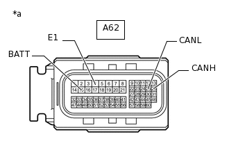
*a
Front view of wire harness connector
(to ECM)
Disconnect the ECM connector.
Measure the resistance according to the value(s) in the table below.
Terminal No. (Symbol)
Wiring Color
Terminal Description
Condition
Specified Condition
A62-26 (CANH) - A62-25 (CANL)
Y - W
HIGH-level CAN bus wire - LOW-level CAN bus wire
Cable disconnected from negative (-) battery terminal
108 to 132 Ω
A62-26 (CANH) - A62-4 (E1)
Y - W-B
HIGH-level CAN bus wire - GND
Cable disconnected from negative (-) battery terminal
200 Ω or higher
A62-25 (CANL) - A62-4 (E1)
W - W-B
LOW-level CAN bus wire - GND
Cable disconnected from negative (-) battery terminal
200 Ω or higher
A62-26 (CANH) - A62-15 (BATT)
Y - W
HIGH-level CAN bus wire - Battery positive (+)
Cable disconnected from negative (-) battery terminal
6 kΩ or higher
A62-25 (CANL) - A62-15 (BATT)
W - W
LOW-level CAN bus wire - Battery positive (+)
Cable disconnected from negative (-) battery terminal
6 kΩ or higher
-
for 2AD-FTV, 2AD-FHV, 2AD-CCo, 2AD-DPF:
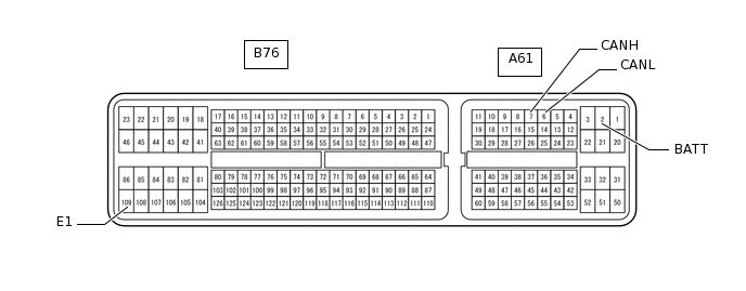
Disconnect the ECM connectors.
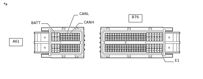
*a
Front view of wire harness connector
(to ECM)
-
-
Measure the resistance according to the value(s) in the table below.
Terminal No. (Symbol)
Wiring Color
Terminal Description
Condition
Specified Condition
A61-7 (CANH) - A61-6 (CANL)
Y - W
HIGH-level CAN bus wire - LOW-level CAN bus wire
Cable disconnected from negative (-) battery terminal
108 to 132 Ω
A61-7 (CANH) - B76-109 (E1)
Y - BR
HIGH-level CAN bus wire - GND
Cable disconnected from negative (-) battery terminal
200 Ω or higher
A61-6 (CANL) - B76-109 (E1)
W - BR
LOW-level CAN bus wire - GND
Cable disconnected from negative (-) battery terminal
200 Ω or higher
A61-7 (CANH) - A61-2 (BATT)
Y - W
HIGH-level CAN bus wire - Battery positive (+)
Cable disconnected from negative (-) battery terminal
6 kΩ or higher
A61-6 (CANL) - A61-2 (BATT)
W - W
LOW-level CAN bus wire - Battery positive (+)
Cable disconnected from negative (-) battery terminal
6 kΩ or higher
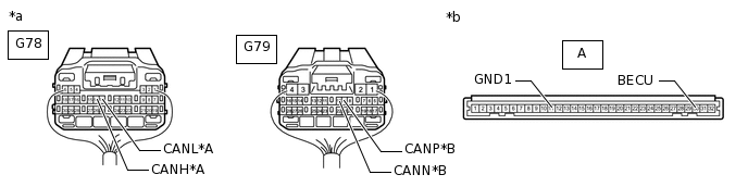
CHECK MAIN BODY ECU (MULTIPLEX NETWORK BODY ECU) AND INSTRUMENT PANEL JUNCTION BLOCK ASSEMBLY
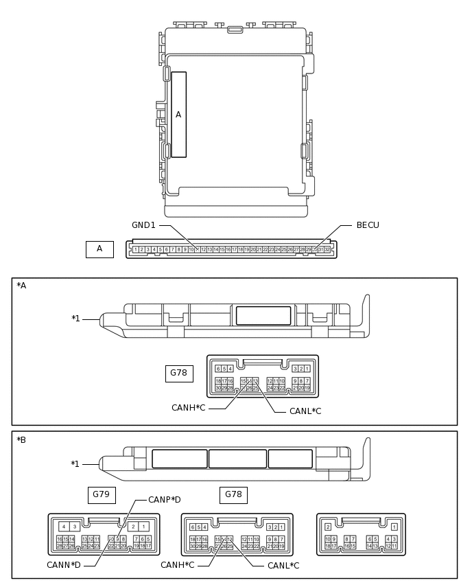
*A
Main Body ECU (Multiplex Network Body ECU) with 1 Connector
*B
Main Body ECU (Multiplex Network Body ECU) with 3 Connectors
*C
Bus 2
*D
Sub Bus 1
*1
Main Body ECU (Multiplex Network Body ECU)
-
-
Remove the main body ECU (multiplex network body ECU).
*A
Bus 2
*B
Sub Bus 1
*a
Rear view of wire harness connector
(to Main Body ECU [Multiplex Network Body ECU])
*b
Front view of wire harness connector
(to Main Body ECU [Multiplex Network Body ECU])
Reconnect the instrument panel junction block assembly connectors.
Measure the resistance according to the value(s) in the table below.
Table 11. Bus 2 Terminal No. (Symbol)
Wiring Color
Terminal Description
Condition
Specified Condition
G78-14 (CANH) - G78-13 (CANL)
G - W
HIGH-level CAN bus wire - LOW-level CAN bus wire
Cable disconnected from negative (-) battery terminal
54 to 69 Ω
G78-14 (CANH) - A-11 (GND1)
G - None
HIGH-level CAN bus wire - GND
Cable disconnected from negative (-) battery terminal
200 Ω or higher
G78-13 (CANL) - A-11 (GND1)
W - None
LOW-level CAN bus wire - GND
Cable disconnected from negative (-) battery terminal
200 Ω or higher
G78-14 (CANH) - A-30 (BECU)
G - None
HIGH-level CAN bus wire - Battery positive (+)
Cable disconnected from negative (-) battery terminal
6 kΩ or higher
G78-13 (CANL) - A-30 (BECU)
W - None
LOW-level CAN bus wire - Battery positive (+)
Cable disconnected from negative (-) battery terminal
6 kΩ or higher
Table 12. Sub Bus 1 Terminal No. (Symbol)
Wiring Color
Terminal Description
Condition
Specified Condition
G79-9 (CANP) - G79-10 (CANN)
B - GR
HIGH-level CAN bus wire - LOW-level CAN bus wire
Cable disconnected from negative (-) battery terminal
108 to 132 Ω
G79-9 (CANP) - A-11 (GND1)
B - None
HIGH-level CAN bus wire - GND
Cable disconnected from negative (-) battery terminal
200 Ω or higher
G79-10 (CANN) - A-11 (GND1)
GR - None
LOW-level CAN bus wire - GND
Cable disconnected from negative (-) battery terminal
200 Ω or higher
G79-9 (CANP) - A-30 (BECU)
B - None
HIGH-level CAN bus wire - Battery positive (+)
Cable disconnected from negative (-) battery terminal
6 kΩ or higher
G79-10 (CANN) - A-30 (BECU)
GR - None
LOW-level CAN bus wire - Battery positive (+)
Cable disconnected from negative (-) battery terminal
6 kΩ or higher
CHECK COMBINATION METER ASSEMBLY

-
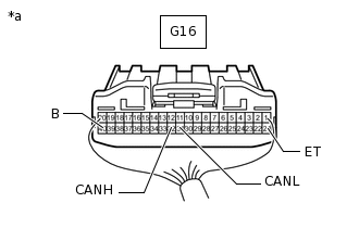
*a
Rear view of wire harness connector
(to Combination Meter Assembly)
Disconnect the combination meter assembly connector.
Measure the resistance according to the value(s) in the table below.
Terminal No. (Symbol)
Wiring Color
Terminal Description
Condition
Specified Condition
G16-32 (CANH) - G16-31 (CANL)
G - W
HIGH-level CAN bus wire - LOW-level CAN bus wire
Cable disconnected from negative (-) battery terminal
108 to 132 Ω
G16-32 (CANH) - G16-21 (ET)
G - BR
HIGH-level CAN bus wire - GND
Cable disconnected from negative (-) battery terminal
200 Ω or higher
G16-31 (CANL) - G16-21 (ET)
W - BR
LOW-level CAN bus wire - GND
Cable disconnected from negative (-) battery terminal
200 Ω or higher
G16-32 (CANH) - G16-40 (B)
G - Y
HIGH-level CAN bus wire - Battery positive (+)
Cable disconnected from negative (-) battery terminal
6 kΩ or higher
G16-31 (CANL) - G16-40 (B)
W - Y
LOW-level CAN bus wire - Battery positive (+)
Cable disconnected from negative (-) battery terminal
6 kΩ or higher
-
CHECK AIRBAG SENSOR ASSEMBLY
Figure 1. w/ Occupant Classification System: 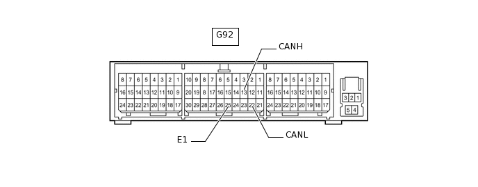
Figure 2. w/o Occupant Classification System: 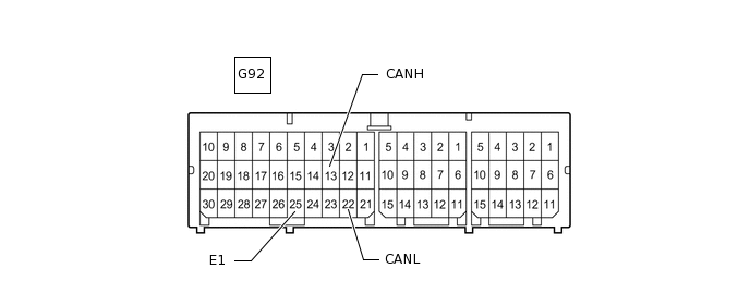
-
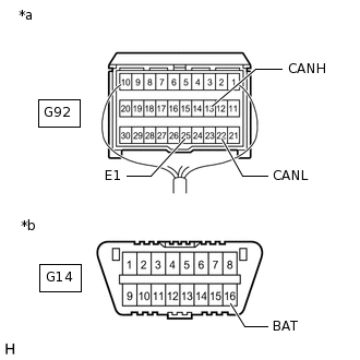
*a
Rear view of wire harness connector
(to Airbag Sensor Assembly)
*b
Front view of DLC3
Disconnect the airbag sensor assembly connector.
Measure the resistance according to the value(s) in the table below.
Terminal No. (Symbol)
Wiring Color
Terminal Description
Condition
Specified Condition
G92-13 (CANH) - G92-22 (CANL)
BR - W
HIGH-level CAN bus wire - LOW-level CAN bus wire
Cable disconnected from negative (-) battery terminal
54 to 69 Ω
G92-13 (CANH) - G92-25 (E1)
BR - W-B
HIGH-level CAN bus wire - GND
Cable disconnected from negative (-) battery terminal
200 Ω or higher
G92-22 (CANL) - G92-25 (E1)
W - W-B
LOW-level CAN bus wire - GND
Cable disconnected from negative (-) battery terminal
200 Ω or higher
G92-13 (CANH) - G14-16 (BAT)
BR - L
HIGH-level CAN bus wire - Battery positive (+)
Cable disconnected from negative (-) battery terminal
6 kΩ or higher
G92-22 (CANL) - G14-16 (BAT)
W - L
LOW-level CAN bus wire - Battery positive (+)
Cable disconnected from negative (-) battery terminal
6 kΩ or higher
-
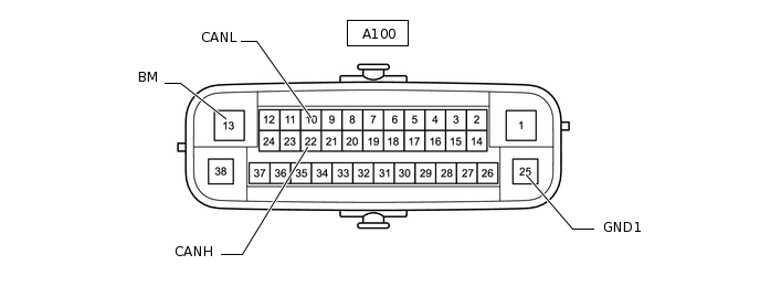
CHECK BRAKE ACTUATOR ASSEMBLY (SKID CONTROL ECU)
-
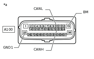
*a
Front view of wire harness connector
(to Brake Actuator Assembly [Skid Control ECU])
Disconnect the brake actuator assembly (skid control ECU) connector.
Measure the resistance according to the value(s) in the table below.
Terminal No. (Symbol)
Wiring Color
Terminal Description
Condition
Specified Condition
A100-22 (CANH) - A100-10 (CANL)
B - W
HIGH-level CAN bus wire - LOW-level CAN bus wire
Cable disconnected from negative (-) battery terminal
54 to 69 Ω
A100-22 (CANH) - A100-1 (GND1)
B - W-B
HIGH-level CAN bus wire - GND
Cable disconnected from negative (-) battery terminal
200 Ω or higher
A100-10 (CANL) - A100-1 (GND1)
W - W-B
LOW-level CAN bus wire - GND
Cable disconnected from negative (-) battery terminal
200 Ω or higher
A100-22 (CANH) - A100-13 (BM)
B - B
HIGH-level CAN bus wire - Battery positive (+)
Cable disconnected from negative (-) battery terminal
6 kΩ or higher
A100-10 (CANL) - A100-13 (BM)
W - B
LOW-level CAN bus wire - Battery positive (+)
Cable disconnected from negative (-) battery terminal
6 kΩ or higher
-
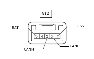
CHECK SPIRAL WITH SENSOR CABLE SUB-ASSEMBLY (STEERING ANGLE SENSOR)
-
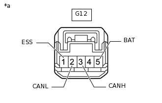
*a
Front view of wire harness connector
(to Spiral with Sensor Cable Sub-assembly [Steering Angle Sensor])
Disconnect the spiral with sensor cable sub-assembly (steering angle sensor) connector.
Measure the resistance according to the value(s) in the table below.
Terminal No. (Symbol)
Wiring Color
Terminal Description
Condition
Specified Condition
G12-3 (CANH) - G12-2 (CANL)
P - W
HIGH-level CAN bus wire - LOW-level CAN bus wire
Cable disconnected from negative (-) battery terminal
54 to 69 Ω
G12-3 (CANH) - G12-1 (ESS)
P - BR
HIGH-level CAN bus wire - GND
Cable disconnected from negative (-) battery terminal
200 Ω or higher
G12-2 (CANL) - G12-1 (ESS)
W - BR
LOW-level CAN bus wire - GND
Cable disconnected from negative (-) battery terminal
200 Ω or higher
G12-3 (CANH) - G12-5 (BAT)
P - SB
HIGH-level CAN bus wire - Battery positive (+)
Cable disconnected from negative (-) battery terminal
6 kΩ or higher
G12-2 (CANL) - G12-5 (BAT)
W - SB
LOW-level CAN bus wire - Battery positive (+)
Cable disconnected from negative (-) battery terminal
6 kΩ or higher
-
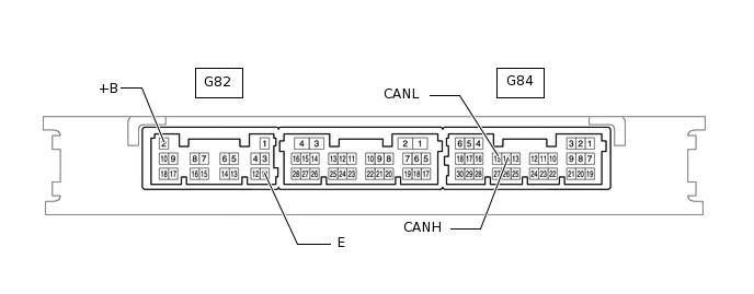
CHECK CERTIFICATION ECU (SMART KEY ECU ASSEMBLY) (w/ Entry and Start System)
-
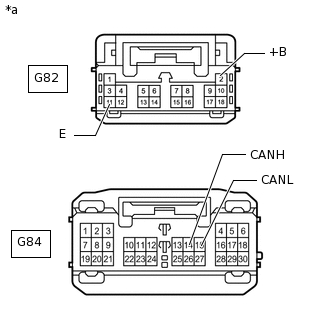
*a
Front view of wire harness connector
(to Certification ECU [Smart Key ECU Assembly])
Disconnect the certification ECU (smart key ECU assembly) connectors.
Measure the resistance according to the value(s) in the table below.
Terminal No. (Symbol)
Wiring Color
Terminal Description
Condition
Specified Condition
G84-14 (CANH) - G84-15 (CANL)
R - W
HIGH-level CAN bus wire - LOW-level CAN bus wire
Cable disconnected from negative (-) battery terminal
54 to 69 Ω
G84-14 (CANH) - G82-11 (E)
R - BR
HIGH-level CAN bus wire - GND
Cable disconnected from negative (-) battery terminal
200 Ω or higher
G84-15 (CANL) - G82-11 (E)
W - BR
LOW-level CAN bus wire - GND
Cable disconnected from negative (-) battery terminal
200 Ω or higher
G84-14 (CANH) - G82-2 (+B)
R - W
HIGH-level CAN bus wire - Battery positive (+)
Cable disconnected from negative (-) battery terminal
6 kΩ or higher
G84-15 (CANL) - G82-2 (+B)
W - W
LOW-level CAN bus wire - Battery positive (+)
Cable disconnected from negative (-) battery terminal
6 kΩ or higher
-
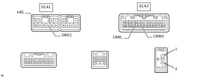
CHECK RADIO AND DISPLAY RECEIVER ASSEMBLY (w/ Audio and Visual System [for Radio and Display Type])
-
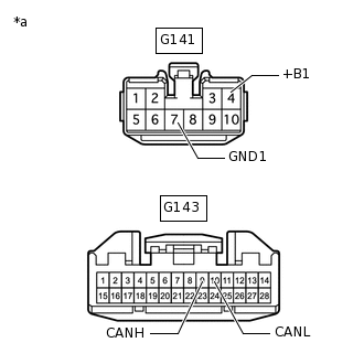
*a
Front view of wire harness connector
(to Radio and Display Receiver Assembly)
Disconnect the radio and display receiver assembly connectors.
Measure the resistance according to the value(s) in the table below.
Terminal No. (Symbol)
Wiring Color
Terminal Description
Condition
Specified Condition
G143-9 (CANH) - G143-10 (CANL)
Y - W
HIGH-level CAN bus wire - LOW-level CAN bus wire
Cable disconnected from negative (-) battery terminal
54 to 69 Ω
G143-9 (CANH) - G141-7 (GND1)
Y - BR
HIGH-level CAN bus wire - GND
Cable disconnected from negative (-) battery terminal
200 Ω or higher
G143-10 (CANL) - G141-7 (GND1)
W - BR
LOW-level CAN bus wire - GND
Cable disconnected from negative (-) battery terminal
200 Ω or higher
G143-9 (CANH) - G141-4 (+B1)
Y - SB
HIGH-level CAN bus wire - Battery positive (+)
Cable disconnected from negative (-) battery terminal
6 kΩ or higher
G143-10 (CANL) - G141-4 (+B1)
W - SB
LOW-level CAN bus wire - Battery positive (+)
Cable disconnected from negative (-) battery terminal
6 kΩ or higher
-
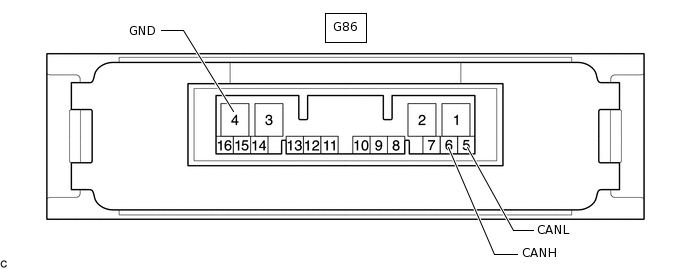
CHECK 4WD ECU ASSEMBLY (for 4WD/AWD)
-
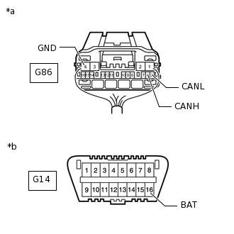
*a
Rear view of wire harness connector
(to 4WD ECU Assembly)
*b
Front view of DLC3
Disconnect the 4WD ECU assembly connector.
Measure the resistance according to the value(s) in the table below.
Terminal No. (Symbol)
Wiring Color
Terminal Description
Condition
Specified Condition
G86-6 (CANH) - G86-5 (CANL)
GR - W
HIGH-level CAN bus wire - LOW-level CAN bus wire
Cable disconnected from negative (-) battery terminal
54 to 69 Ω
G86-6 (CANH) - G86-4 (GND)
GR - W-B
HIGH-level CAN bus wire - GND
Cable disconnected from negative (-) battery terminal
200 Ω or higher
G86-5 (CANL) - G86-4 (GND)
W - W-B
LOW-level CAN bus wire - GND
Cable disconnected from negative (-) battery terminal
200 Ω or higher
G86-6 (CANH) - G14-16 (BAT)
GR - L
HIGH-level CAN bus wire - Battery positive (+)
Cable disconnected from negative (-) battery terminal
6 kΩ or higher
G86-5 (CANL) - G14-16 (BAT)
W - L
LOW-level CAN bus wire - Battery positive (+)
Cable disconnected from negative (-) battery terminal
6 kΩ or higher
-
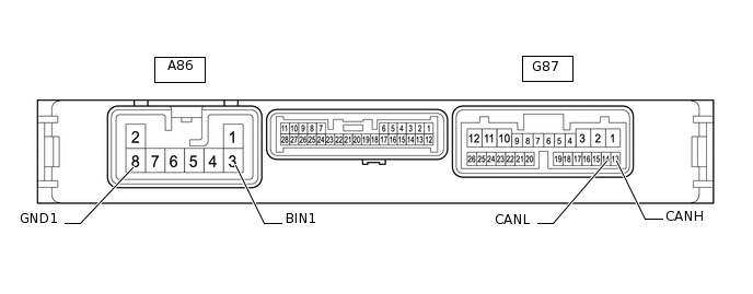
CHECK ENGINE STOP AND START ECU (w/ Stop and Start System)
-
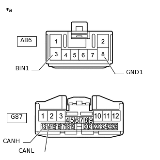
*a
Front view of wire harness connector
(to Engine Stop and Start ECU)
Disconnect the engine stop and start ECU connectors.
Measure the resistance according to the value(s) in the table below.
Terminal No. (Symbol)
Wiring Color
Terminal Description
Condition
Specified Condition
G87-13 (CANH) - G87-14 (CANL)
LG - W
HIGH-level CAN bus wire - LOW-level CAN bus wire
Cable disconnected from negative (-) battery terminal
54 to 69 Ω
G87-13 (CANH) - A86-8 (GND1)
LG - W-B
HIGH-level CAN bus wire - GND
Cable disconnected from negative (-) battery terminal
200 Ω or higher
G87-14 (CANL) - A86-8 (GND1)
W - W-B
LOW-level CAN bus wire - GND
Cable disconnected from negative (-) battery terminal
200 Ω or higher
G87-13 (CANH) - A86-3 (BIN1)
LG - L
HIGH-level CAN bus wire - Battery positive (+)
Cable disconnected from negative (-) battery terminal
6 kΩ or higher
G87-14 (CANL) - A86-3 (BIN1)
W - L
LOW-level CAN bus wire - Battery positive (+)
Cable disconnected from negative (-) battery terminal
6 kΩ or higher
-
-
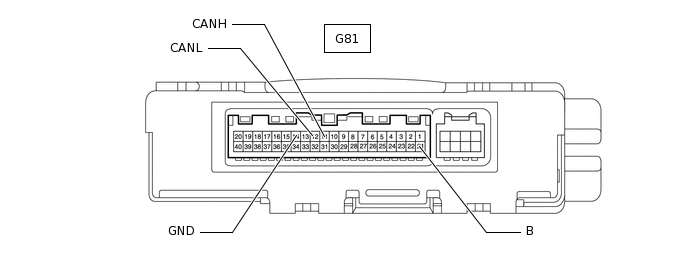
CHECK AIR CONDITIONING AMPLIFIER ASSEMBLY
-
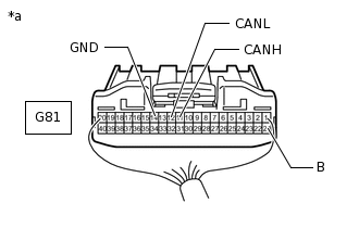
*a
Rear view of wire harness connector
(to Air Conditioning Amplifier Assembly)
Disconnect the air conditioning amplifier assembly connector.
Measure the resistance according to the value(s) in the table below.
Terminal No. (Symbol)
Wiring Color
Terminal Description
Condition
Specified Condition
G81-11 (CANH) - G81-12 (CANL)
B - W
HIGH-level CAN bus wire - LOW-level CAN bus wire
Cable disconnected from negative (-) battery terminal
54 to 69 Ω
G81-11 (CANH) - G81-14 (GND)
B - W-B
HIGH-level CAN bus wire - GND
Cable disconnected from negative (-) battery terminal
200 Ω or higher
G81-12 (CANL) - G81-14 (GND)
W - W-B
LOW-level CAN bus wire - GND
Cable disconnected from negative (-) battery terminal
200 Ω or higher
G81-11 (CANH) - G81-21 (B)
B - GR
HIGH-level CAN bus wire - Battery positive (+)
Cable disconnected from negative (-) battery terminal
6 kΩ or higher
G81-12 (CANL) - G81-21 (B)
W - GR
LOW-level CAN bus wire - Battery positive (+)
Cable disconnected from negative (-) battery terminal
6 kΩ or higher
-
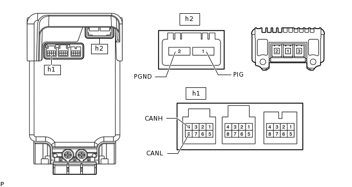
CHECK POWER STEERING ECU ASSEMBLY
-
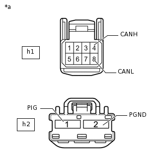
*a
Front view of wire harness connector
(to Power Steering ECU Assembly)
Disconnect the power steering ECU assembly connectors.
Measure the resistance according to the value(s) in the table below.
Terminal No. (Symbol)
Wiring Color
Terminal Description
Condition
Specified Condition
h1-4 (CANH) - h1-8 (CANL)
W - B
HIGH-level CAN bus wire - LOW-level CAN bus wire
Cable disconnected from negative (-) battery terminal
54 to 69 Ω
h1-4 (CANH) - h2-2 (PGND)
W - R
HIGH-level CAN bus wire - GND
Cable disconnected from negative (-) battery terminal
200 Ω or higher
h1-8 (CANL) - h2-2 (PGND)
B - R
LOW-level CAN bus wire - GND
Cable disconnected from negative (-) battery terminal
200 Ω or higher
h1-4 (CANH) - h2-1 (PIG)
W - R
HIGH-level CAN bus wire - Battery positive (+)
Cable disconnected from negative (-) battery terminal
6 kΩ or higher
h1-8 (CANL) - h2-1 (PIG)
B - R
LOW-level CAN bus wire - Battery positive (+)
Cable disconnected from negative (-) battery terminal
6 kΩ or higher
-
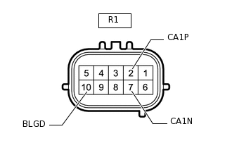
CHECK BLIND SPOT MONITOR SENSOR LH (w/ Blind Spot Monitor System)
-
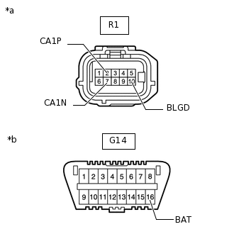
*a
Front view of wire harness connector
(to Blind Spot Monitor Sensor LH)
*b
Front view of DLC3
Disconnect the blind spot monitor sensor LH connector.
Measure the resistance according to the value(s) in the table below.
Terminal No. (Symbol)
Wiring Color
Terminal Description
Condition
Specified Condition
R1-2 (CA1P) - R1-7 (CA1N)
R - LG
HIGH-level CAN bus wire - LOW-level CAN bus wire
Cable disconnected from negative (-) battery terminal
54 to 69 Ω
R1-2 (CA1P) - R1-10 (BLGD)
R - W-B
HIGH-level CAN bus wire - GND
Cable disconnected from negative (-) battery terminal
200 Ω or higher
R1-7 (CA1N) - R1-10 (BLGD)
LG - W-B
LOW-level CAN bus wire - GND
Cable disconnected from negative (-) battery terminal
200 Ω or higher
R1-2 (CA1P) - G14-16 (BAT)
R - L
HIGH-level CAN bus wire - Battery positive (+)
Cable disconnected from negative (-) battery terminal
6 kΩ or higher
R1-7 (CA1N) - G14-16 (BAT)
LG - L
LOW-level CAN bus wire - Battery positive (+)
Cable disconnected from negative (-) battery terminal
6 kΩ or higher
-
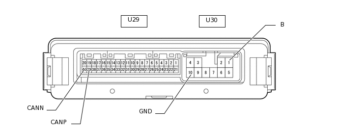
CHECK MULTIPLEX NETWORK DOOR ECU (w/ Power Back Door System)
-
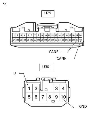
*a
Front view of wire harness connector
(to Multiplex Network Door ECU)
Disconnect the multiplex network door ECU connectors.
Measure the resistance according to the value(s) in the table below.
Terminal No. (Symbol)
Wiring Color
Terminal Description
Condition
Specified Condition
U29-39 (CANP) - U29-40 (CANN)
G - GR
HIGH-level CAN bus wire - LOW-level CAN bus wire
Cable disconnected from negative (-) battery terminal
54 to 69 Ω
U29-39 (CANP) - U30-10 (GND)
G - W-B
HIGH-level CAN bus wire - GND
Cable disconnected from negative (-) battery terminal
200 Ω or higher
U29-40 (CANN) - U30-10 (GND)
GR - W-B
LOW-level CAN bus wire - GND
Cable disconnected from negative (-) battery terminal
200 Ω or higher
U29-39 (CANP) - U30-1 (B)
G - W
HIGH-level CAN bus wire - Battery positive (+)
Cable disconnected from negative (-) battery terminal
6 kΩ or higher
U29-40 (CANN) - U30-1 (B)
GR - W
LOW-level CAN bus wire - Battery positive (+)
Cable disconnected from negative (-) battery terminal
6 kΩ or higher
-
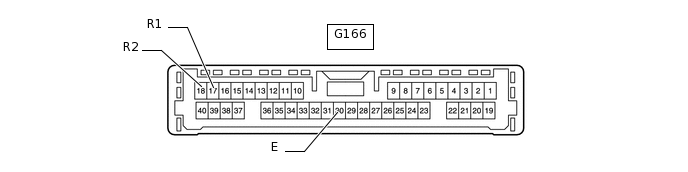
CHECK CLEARANCE WARNING ECU ASSEMBLY (w/ TOYOTA Parking Assist-sensor System [for 8 Sensor Type])
-
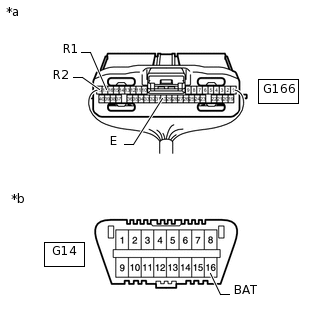
*a
Rear view of wire harness connector
(to Clearance Warning ECU Assembly)
*b
Front view of DLC3
Disconnect the clearance warning ECU assembly connector.
Measure the resistance according to the value(s) in the table below.
Terminal No. (Symbol)
Wiring Color
Terminal Description
Condition
Specified Condition
G166-17 (R1) - G166-18 (R2)
R - LG
HIGH-level CAN bus wire - LOW-level CAN bus wire
Cable disconnected from negative (-) battery terminal
54 to 69 Ω
G166-17 (R1) - G166-30 (E)
R - W-B
HIGH-level CAN bus wire - GND
Cable disconnected from negative (-) battery terminal
200 Ω or higher
G166-18 (R2) - G166-30 (E)
LG - W-B
LOW-level CAN bus wire - GND
Cable disconnected from negative (-) battery terminal
200 Ω or higher
G166-17 (R1) - G14-16 (BAT)
R - L
HIGH-level CAN bus wire - Battery positive (+)
Cable disconnected from negative (-) battery terminal
6 kΩ or higher
G166-18 (R2) - G14-16 (BAT)
LG - L
LOW-level CAN bus wire - Battery positive (+)
Cable disconnected from negative (-) battery terminal
6 kΩ or higher
-
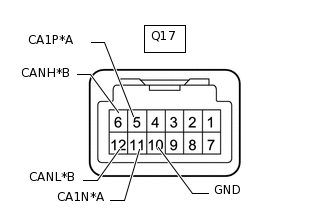
CHECK FORWARD RECOGNITION CAMERA (w/ Pre-crash Safety System)
*A
Bus 5
*B
Local Bus
-
*A
Bus 5
*B
Local Bus
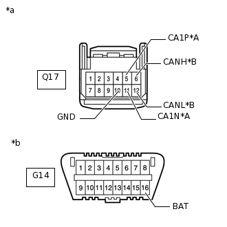
*a
Front view of wire harness connector
(to Forward Recognition Camera)
*b
Front view of DLC3
Disconnect the forward recognition camera connector.
Measure the resistance according to the value(s) in the table below.
Table 13. Bus 5 Terminal No. (Symbol)
Wiring Color
Terminal Description
Condition
Specified Condition
Q17-5 (CA1P) - Q17-11 (CA1N)
G - LG
HIGH-level CAN bus wire - LOW-level CAN bus wire
Cable disconnected from negative (-) battery terminal
54 to 69 Ω
Q17-5 (CA1P) - Q17-10 (GND)
G - W-B
HIGH-level CAN bus wire - GND
Cable disconnected from negative (-) battery terminal
200 Ω or higher
Q17-11 (CA1N) - Q17-10 (GND)
LG - W-B
LOW-level CAN bus wire - GND
Cable disconnected from negative (-) battery terminal
200 Ω or higher
Q17-5 (CA1P) - G14-16 (BAT)
G - L
HIGH-level CAN bus wire - Battery positive (+)
Cable disconnected from negative (-) battery terminal
6 kΩ or higher
Q17-11 (CA1N) - G14-16 (BAT)
LG - L
LOW-level CAN bus wire - Battery positive (+)
Cable disconnected from negative (-) battery terminal
6 kΩ or higher
Table 14. Local Bus Terminal No. (Symbol)
Wiring Color
Terminal Description
Condition
Specified Condition
Q17-6 (CANH) - Q17-12 (CANL)
L - W
HIGH-level CAN bus wire - LOW-level CAN bus wire
Cable disconnected from negative (-) battery terminal
108 to 132 Ω
Q17-6 (CANH) - Q17-10 (GND)
L - W-B
HIGH-level CAN bus wire - GND
Cable disconnected from negative (-) battery terminal
200 Ω or higher
Q17-12 (CANL) - Q17-10 (GND)
W - W-B
LOW-level CAN bus wire - GND
Cable disconnected from negative (-) battery terminal
200 Ω or higher
Q17-6 (CANH) - G14-16 (BAT)
L - L
HIGH-level CAN bus wire - Battery positive (+)
Cable disconnected from negative (-) battery terminal
6 kΩ or higher
Q17-12 (CANL) - G14-16 (BAT)
W - L
LOW-level CAN bus wire - Battery positive (+)
Cable disconnected from negative (-) battery terminal
6 kΩ or higher
-
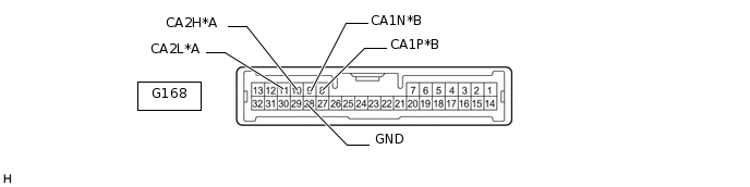
CHECK DRIVING SUPPORT ECU ASSEMBLY (w/ Pre-crash Safety System)
*A
Bus 5
*B
Local Bus
-
*A
Bus 5
*B
Local Bus
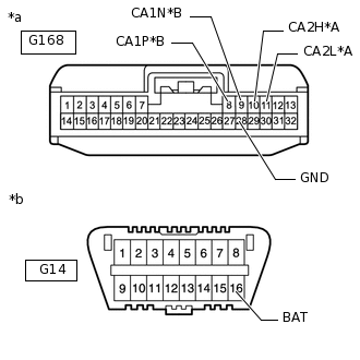
*a
Front view of wire harness connector
(to Driving Support ECU Assembly)
*b
Front view of DLC3
Disconnect the driving support ECU assembly connector.
Measure the resistance according to the value(s) in the table below.
Table 15. Bus 5 Terminal No. (Symbol)
Wiring Color
Terminal Description
Condition
Specified Condition
G168-10 (CA2H) - G168-11 (CA2L)
P - LG
HIGH-level CAN bus wire - LOW-level CAN bus wire
Cable disconnected from negative (-) battery terminal
54 to 69 Ω
G168-10 (CA2H) - G168-28 (GND)
P - BR
HIGH-level CAN bus wire - GND
Cable disconnected from negative (-) battery terminal
200 Ω or higher
G168-11 (CA2L) - G168-28 (GND)
LG - BR
LOW-level CAN bus wire - GND
Cable disconnected from negative (-) battery terminal
200 Ω or higher
G168-10 (CA2H) - G14-16 (BAT)
P - L
HIGH-level CAN bus wire - Battery positive (+)
Cable disconnected from negative (-) battery terminal
6 kΩ or higher
G168-11 (CA2L) - G14-16 (BAT)
LG - L
LOW-level CAN bus wire - Battery positive (+)
Cable disconnected from negative (-) battery terminal
6 kΩ or higher
Table 16. Local Bus Terminal No. (Symbol)
Wiring Color
Terminal Description
Condition
Specified Condition
G168-8 (CA1P) - G168-9 (CA1N)
B - W
HIGH-level CAN bus wire - LOW-level CAN bus wire
Cable disconnected from negative (-) battery terminal
54 to 69 Ω
G168-8 (CA1P) - G168-28 (GND)
B - BR
HIGH-level CAN bus wire - GND
Cable disconnected from negative (-) battery terminal
200 Ω or higher
G168-9 (CA1N) - G168-28 (GND)
W - BR
LOW-level CAN bus wire - GND
Cable disconnected from negative (-) battery terminal
200 Ω or higher
G168-8 (CA1P) - G14-16 (BAT)
B - L
HIGH-level CAN bus wire - Battery positive (+)
Cable disconnected from negative (-) battery terminal
6 kΩ or higher
G168-9 (CA1N) - G14-16 (BAT)
W - L
LOW-level CAN bus wire - Battery positive (+)
Cable disconnected from negative (-) battery terminal
6 kΩ or higher
-
CHECK MILLIMETER WAVE RADAR SENSOR ASSEMBLY (w/ Pre-crash Safety System)

*A
Bus 5
*B
Local Bus
-
*A
Bus 5
*B
Local Bus
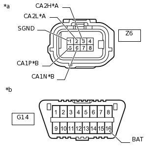
*a
Front view of wire harness connector
(to Millimeter Wave Radar Sensor Assembly)
*b
Front view of DLC3
Disconnect the millimeter wave radar sensor assembly connector.
Measure the resistance according to the value(s) in the table below.
Table 17. Bus 5 Terminal No. (Symbol)
Wiring Color
Terminal Description
Condition
Specified Condition
Z6-3 (CA2H) - Z6-2 (CA2L)
B - LG
HIGH-level CAN bus wire - LOW-level CAN bus wire
Cable disconnected from negative (-) battery terminal
54 to 69 Ω
Z6-3 (CA2H) - Z6-1 (SGND)
B - BR
HIGH-level CAN bus wire - GND
Cable disconnected from negative (-) battery terminal
200 Ω or higher
Z6-2 (CA2L) - Z6-1 (SGND)
LG - BR
LOW-level CAN bus wire - GND
Cable disconnected from negative (-) battery terminal
200 Ω or higher
Z6-3 (CA2H) - G14-16 (BAT)
B - L
HIGH-level CAN bus wire - Battery positive (+)
Cable disconnected from negative (-) battery terminal
6 kΩ or higher
Z6-2 (CA2L) - G14-16 (BAT)
LG - L
LOW-level CAN bus wire - Battery positive (+)
Cable disconnected from negative (-) battery terminal
6 kΩ or higher
Table 18. Local Bus Terminal No. (Symbol)
Wiring Color
Terminal Description
Condition
Specified Condition
Z6-5 (CA1P) - Z6-6 (CA1N)
SB - W
HIGH-level CAN bus wire - LOW-level CAN bus wire
Cable disconnected from negative (-) battery terminal
108 to 132 Ω
Z6-5 (CA1P) - Z6-1 (SGND)
SB - BR
HIGH-level CAN bus wire - GND
Cable disconnected from negative (-) battery terminal
200 Ω or higher
Z6-6 (CA1N) - Z6-1 (SGND)
W - BR
LOW-level CAN bus wire - GND
Cable disconnected from negative (-) battery terminal
200 Ω or higher
Z6-5 (CA1P) - G14-16 (BAT)
SB - L
HIGH-level CAN bus wire - Battery positive (+)
Cable disconnected from negative (-) battery terminal
6 kΩ or higher
Z6-6 (CA1N) - G14-16 (BAT)
W - L
LOW-level CAN bus wire - Battery positive (+)
Cable disconnected from negative (-) battery terminal
6 kΩ or higher
-
CHECK TELEVISION CAMERA ASSEMBLY (w/ Parking Assist Monitor System [for Camera built-in ECU])

-
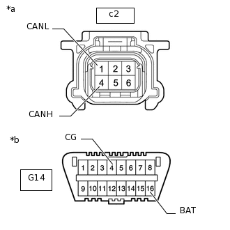
*a
Front view of wire harness connector
(to Television Camera Assembly)
*b
Front view of DLC3
Disconnect the television camera assembly connector.
Measure the resistance according to the value(s) in the table below.
Terminal No. (Symbol)
Wiring Color
Terminal Description
Condition
Specified Condition
c2-4 (CANH) - c2-1 (CANL)
P - G
HIGH-level CAN bus wire - LOW-level CAN bus wire
Cable disconnected from negative (-) battery terminal
54 to 69 Ω
c2-4 (CANH) - G14-4 (CG)
P - BR
HIGH-level CAN bus wire - GND
Cable disconnected from negative (-) battery terminal
200 Ω or higher
c2-1 (CANL) - G14-4 (CG)
G - BR
LOW-level CAN bus wire - GND
Cable disconnected from negative (-) battery terminal
200 Ω or higher
c2-4 (CANH) - G14-16 (BAT)
P - L
HIGH-level CAN bus wire - Battery positive (+)
Cable disconnected from negative (-) battery terminal
6 kΩ or higher
c2-1 (CANL) - G14-16 (BAT)
G - L
LOW-level CAN bus wire - Battery positive (+)
Cable disconnected from negative (-) battery terminal
6 kΩ or higher
-
-
CHECK PARKING ASSIST ECU (w/ Panoramic View Monitor System)
-
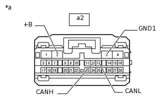
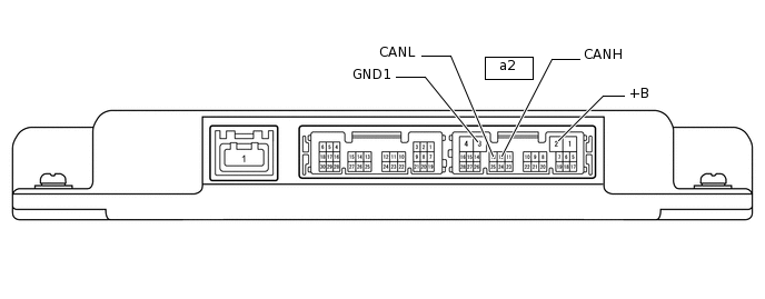
*a
Front view of wire harness connector
(to Parking Assist ECU)
Disconnect the parking assist ECU connector.
Measure the resistance according to the value(s) in the table below.
Terminal No. (Symbol)
Wiring Color
Terminal Description
Condition
Specified Condition
a2-12 (CANH) - a2-13 (CANL)
G - LG
HIGH-level CAN bus wire - LOW-level CAN bus wire
Cable disconnected from negative (-) battery terminal
54 to 69 Ω
a2-12 (CANH) - a2-3 (GND1)
G - BR
HIGH-level CAN bus wire - GND
Cable disconnected from negative (-) battery terminal
200 Ω or higher
a2-13 (CANL) - a2-3 (GND1)
LG - BR
LOW-level CAN bus wire - GND
Cable disconnected from negative (-) battery terminal
200 Ω or higher
a2-12 (CANH) - a2-2 (+B)
G - SB
HIGH-level CAN bus wire - Battery positive (+)
Cable disconnected from negative (-) battery terminal
6 kΩ or higher
a2-13 (CANL) - a2-2 (+B)
LG - SB
LOW-level CAN bus wire - Battery positive (+)
Cable disconnected from negative (-) battery terminal
6 kΩ or higher
-
CHECK POSITION CONTROL ECU AND SWITCH ASSEMBLY (w/ Seat Memory)

-
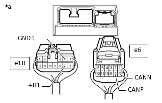
*a
Rear view of wire harness connector
(to Position Control ECU and Switch Assembly)
Disconnect the position control ECU assembly connectors.
Measure the resistance according to the value(s) in the table below.
Terminal No. (Symbol)
Wiring Color
Terminal Description
Condition
Specified Condition
e6-8 (CANP) - e6-7 (CANN)
L - W
HIGH-level CAN bus wire - LOW-level CAN bus wire
Cable disconnected from negative (-) battery terminal
54 to 69 Ω
e6-8 (CANP) - e18-2 (GND1)
L - W-B
HIGH-level CAN bus wire - GND
Cable disconnected from negative (-) battery terminal
200 Ω or higher
e6-7 (CANN) - e18-2 (GND1)
W - W-B
LOW-level CAN bus wire - GND
Cable disconnected from negative (-) battery terminal
200 Ω or higher
e6-8 (CANP) - e18-7 (+B1)
L - W
HIGH-level CAN bus wire - Battery positive (+)
Cable disconnected from negative (-) battery terminal
6 kΩ or higher
e6-7 (CANN) - e18-7 (+B1)
W - W
LOW-level CAN bus wire - Battery positive (+)
Cable disconnected from negative (-) battery terminal
6 kΩ or higher
-
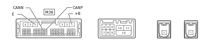
CHECK TELEMATICS TRANSCEIVER (w/ Telematics Transceiver)
-
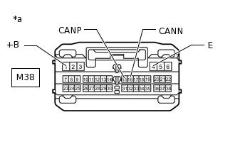
*a
Front view of wire harness connector
(to Telematics Transceiver)
Disconnect the telematics transceiver connector.
Measure the resistance according to the value(s) in the table below.
Terminal No. (Symbol)
Wiring Color
Terminal Description
Condition
Specified Condition
M38-15 (CANP) - M38-16 (CANN)
R - W
HIGH-level CAN bus wire - LOW-level CAN bus wire
Cable disconnected from negative (-) battery terminal
54 to 69 Ω
M38-15 (CANP) - M38-4 (E)
R - W-B
HIGH-level CAN bus wire - GND
Cable disconnected from negative (-) battery terminal
200 Ω or higher
M38-16 (CANN) - M38-4 (E)
W - W-B
LOW-level CAN bus wire - GND
Cable disconnected from negative (-) battery terminal
200 Ω or higher
M38-15 (CANP) - M38-1 (+B)
R - B
HIGH-level CAN bus wire - Battery positive (+)
Cable disconnected from negative (-) battery terminal
6 kΩ or higher
M38-16 (CANN) - M38-1 (+B)
W - B
LOW-level CAN bus wire - Battery positive (+)
Cable disconnected from negative (-) battery terminal
6 kΩ or higher
-