SFI SYSTEM, Diagnostic DTC:P0122,P0123,P0222 and P0223
| DTC Code | DTC Name |
|---|---|
| P0122 | Throttle / Pedal Position Sensor / Switch "A" Circuit Low Input |
| P0123 | Throttle / Pedal Position Sensor / Switch "A" Circuit High Input |
| P0222 | Throttle / Pedal Position Sensor / Switch "B" Circuit Low Input |
| P0223 | Throttle / Pedal Position Sensor / Switch "B" Circuit High Input |
DESCRIPTION
Refer to DTC P0121.
DTC No. |
Detection Item |
DTC Detection Condition |
Trouble Area |
MIL |
Memory |
|---|---|---|---|---|---|
P0122 |
Throttle / Pedal Position Sensor / Switch "A" Circuit Low Input |
Output voltage of VTA1 0.2 V or less for 0.14 seconds or more (1 trip detection logic). |
|
Comes on |
DTC stored |
P0123 |
Throttle / Pedal Position Sensor / Switch "A" Circuit High Input |
Output voltage of VTA1 4.8 V or more for 0.14 seconds or more (1 trip detection logic). |
|
Comes on |
DTC stored |
P0222 |
Throttle / Pedal Position Sensor / Switch "B" Circuit Low Input |
Output voltage of VTA2 0.2 V or less for 0.14 seconds or more (1 trip detection logic). |
|
Comes on |
DTC stored |
P0223 |
Throttle / Pedal Position Sensor / Switch "B" Circuit High Input |
Output voltage of VTA2 4.8 V or more for 0.14 seconds or more (1 trip detection logic). |
|
Comes on |
DTC stored |
WIRING DIAGRAM
Refer to DTC P0121.
CONFIRMATION DRIVING PATTERN
These DTCs are detected when the ignition switch is ON or the engine is running.
CAUTION / NOTICE / HINT
After replacing the ECM and/or throttle body with motor assembly, perform electronic throttle learning and idle learning.
If any DTCs related to the crankshaft position sensor sensor, throttle position sensor and accelerator pedal sensor assembly are output simultaneously, inspect the VC circuit of each component.
Read freeze frame data using the GTS. Freeze frame data records the engine condition when malfunctions are detected. When troubleshooting, freeze frame data can help determine if the vehicle was moving or stationary, if the engine was warmed up or not, if the air fuel ratio was lean or rich, and other data from the time the malfunction occurred.
PROCEDURE
READ VALUE USING GTS (THROTTLE POSITION SENSOR)
Connect the GTS to the DLC3.
Turn the ignition switch to ON.
Turn the GTS on.
Enter the following menus: Powertrain / Engine and ECT / Data List / All Data / Throttle Position No.1 and Throttle Position No.2.
Powertrain > Engine and ECT > Data List
Tester Display
Throttle Position No.1
Throttle Position No.2
Read the values displayed on the GTS.
Result
When Accelerator Pedal Fully Released
When Accelerator Pedal Fully Depressed
Trouble Area
Proceed to
Throttle Position No.1 (VTA1)
Throttle Position No.2 (VTA2)
Throttle Position No.1 (VTA1)
Throttle Position No.2 (VTA2)
4.8 to 4.98 V
0 to 0.2 V
4.8 to 4.98 V
0 to 0.2 V
VC circuit open
A
4.5 to 4.98 V
0 to 0.2 V
4.8 to 4.98 V
0 to 0.2 V
ETA circuit open
0 to 0.2 V, or 4.8 to 4.98 V
3.9 to 4.4 V
0 to 0.2 V, or 4.8 to 4.98 V
3.9 to 4.3 V
VTA1 circuit open or shorted to ground
0.6 to 1.1 V
0 to 0.2 V, or 4.8 to 4.98 V
0.7 to 1.1 V
0 to 0.2 V, or 4.8 to 4.98 V
VTA2 circuit open or shorted to ground
0.6 to 1.1 V
3.9 to 4.4 V
4.2 to 4.54 V
0.46 to 0.76 V
Throttle position sensor circuit normal
B
B CHECK WHETHER DTC OUTPUT RECURS (DTC P0122, P0123, P0222 OR P0223)Click here
CHECK HARNESS AND CONNECTOR (THROTTLE BODY WITH MOTOR ASSEMBLY - ECM)
Disconnect the throttle body with motor assembly connector.
Disconnect the ECM connector.
Measure the resistance according to the value(s) in the table below.
Standard Resistance
Tester Connection
Condition
Specified Condition
B15-5 (VC) - B31-115 (VC)
Always
Below 1 Ω
B15-6 (VTA) - B31-84 (VTA1)
Always
Below 1 Ω
B15-4 (VTA2) - B31-83 (VTA2)
Always
Below 1 Ω
B15-3 (E2) - B31-116 (ETA)
Always
Below 1 Ω
B15-5 (VC) or B31-115 (VC) - Body ground
Always
10 kΩ or higher
B15-6 (VTA) or B31-84 (VTA1) - Body ground
Always
10 kΩ or higher
B15-4 (VTA2) or B31-83 (VTA2) - Body ground
Always
10 kΩ or higher
B15-3 (E2) or B31-116 (ETA) - Body ground
Always
10 kΩ or higher
Result
Proceed to
OK
NG
NG REPAIR OR REPLACE HARNESS OR CONNECTOR
CHECK TERMINAL VOLTAGE (POWER SOURCE OF THROTTLE BODY WITH MOTOR ASSEMBLY)
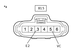
*a
Front view of wire harness connector
(to Throttle Body with Motor Assembly)
Disconnect the throttle body with motor assembly connector.
Turn the ignition switch to ON.
Measure the voltage according to the value(s) in the table below.
Standard Voltage
Tester Connection
Condition
Specified Condition
B15-5 (VC) - B15-3 (E2)
Ignition switch ON
4.5 to 5.5 V
Result
Proceed to
OK
NG
REPLACE THROTTLE BODY WITH MOTOR ASSEMBLY
Replace the throttle body with motor assembly.
Perform electronic throttle learning and idle learning.
Result
Proceed to
NEXT
CHECK WHETHER DTC OUTPUT RECURS (DTC P0122, P0123, P0222 OR P0223)
Connect the GTS to the DLC3.
Turn the ignition switch to ON.
Turn the GTS on.
Clear the DTCs.
Powertrain > Engine and ECT > Clear DTCs
Turn the ignition switch off and wait for at least 30 seconds.
Start the engine.
Turn the GTS on.
Enter the following menus: Powertrain / Engine and ECT / Trouble Codes.
Read the DTCs.
Powertrain > Engine and ECT > Trouble Codes
OK
DTCs are not output
Result
Proceed to
OK
NG
OK END