NAVIGATION SYSTEM(for SD), Diagnostic DTC:B157D
| DTC Code | DTC Name |
|---|---|
| B157D | DAB Tuner Antenna Disconnected |
DESCRIPTION
This DTC is stored when a malfunction occurs in the DAB tuner antenna which is connected to the navigation receiver assembly.
DTC No. |
Detection Item |
DTC Detection Condition |
Trouble Area |
|---|---|---|---|
B157D |
DAB Tuner Antenna Disconnected |
The DAB tuner antenna is not connected |
|
CAUTION / NOTICE / HINT
Check that the wire harness is properly installed and does not have any sharp bends, pinching or loose connections.
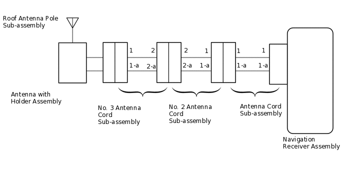
WIRING DIAGRAM
PROCEDURE
CHECK FOR DTC
Clear the DTCs.
Body Electrical > Navigation System > Clear DTCs
Check for DTCs.
Body Electrical > Navigation System > Trouble Codes
OK
No DTCs are output.
Result
Proceed to
OK
NG
CHECK OPTIONAL COMPONENTS
Check if any optional components that may decrease reception capacity, such as a telephone antenna, are installed.
OK
Optional components are installed.
Note:Do not remove optional components without permission of the customer.
Result
Proceed to
OK
NG
OK REMOVE OPTIONAL COMPONENTS AND CHECK AGAIN (SEE NOTICE ABOVE)
CHECK NAVIGATION RECEIVER ASSEMBLY
Remove the antenna connector from the navigation receiver assembly.
Turn the engine switch on (ACC) with the navigation receiver assembly connector connected.
Turn on the radio and turn into AM mode.
Place a screwdriver, thin wire or other metal object on the navigation receiver assembly antenna jack and check that noise can be heard from the speakers.
OK
Noise occurs.
Result
Proceed to
OK
NG
CHECK NO. 3 ANTENNA CORD SUB-ASSEMBLY
-
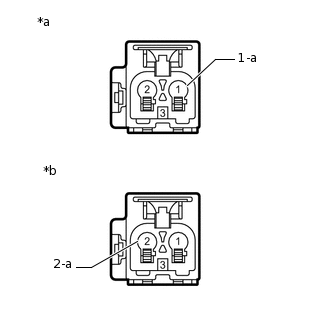
*a
Front view of wire harness connector
(to Antenna with Holder Assembly)
*b
Front view of wire harness connector
(to No. 2 Antenna Cord Sub-assembly)
Disconnect the antenna connector from the antenna with holder assembly.
Disconnect the antenna connector from the No. 2 antenna cord sub-assembly.
Measure the resistance according to the value(s) in the table below.
Standard Resistance
Tester Connection
Condition
Specified Condition
1 - 2
Always
Below 1 Ω
1-a - 2-a
Always
Below 1 Ω
1 - Body ground
Always
10 kΩ or higher
1-a - Body ground
Always
10 kΩ or higher
Result
Proceed to
OK
NG
-
CHECK NO. 2 ANTENNA CORD SUB-ASSEMBLY
-
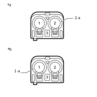
*a
Front view of wire harness connector
(to No. 3 Antenna Cord Sub-assembly)
*b
Front view of wire harness connector
(to Antenna Cord Sub-assembly)
Disconnect the antenna connector from the No. 3 antenna cord sub-assembly.
Disconnect the antenna connector from the antenna cord sub-assembly.
Measure the resistance according to the value(s) in the table below.
Standard Resistance
Tester Connection
Condition
Specified Condition
2 - 1
Always
Below 1 Ω
2-a - 1-a
Always
Below 1 Ω
2 - Body ground
Always
10 kΩ or higher
2-a - Body ground
Always
10 kΩ or higher
Result
Proceed to
OK
NG
-
CHECK ANTENNA CORD SUB-ASSEMBLY
-
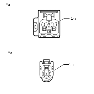
*a
Front view of wire harness connector
(to No. 2 Antenna Cord Sub-assembly)
*b
Front view of wire harness connector
(to Navigation Receiver Assembly)
Disconnect the antenna connector from the No. 2 antenna cord sub-assembly.
Disconnect the antenna connector from the navigation receiver assembly.
Measure the resistance according to the value(s) in the table below.
Standard Resistance
Tester Connection
Condition
Specified Condition
1 - 1
Always
Below 1 Ω
1-a - 1-a
Always
Below 1 Ω
1 - Body ground
Always
10 kΩ or higher
1-a - Body ground
Always
10 kΩ or higher
Result
Proceed to
OK
NG
-
CHECK ROOF ANTENNA POLE SUB-ASSEMBLY
Check that the roof antenna pole sub-assembly is securely installed.
OK
The roof antenna pole sub-assembly is installed properly.
Result
Proceed to
OK
NG
CHECK ANTENNA WITH HOLDER ASSEMBLY
Replace the antenna with holder assembly with a known good one.
Clear the DTCs.
Body Electrical > Navigation System > Clear DTCs
Check for DTCs.
Body Electrical > Navigation System > Trouble Codes
OK
No DTCs are output.
Result
Proceed to
OK
NG
OK END (ANTENNA WITH HOLDER ASSEMBLY IS DEFECTIVE)