СИСТЕМА АВТОМАТИЧЕСКОЙ ТРАНСМИССИИ ДЕТАЛЬНОЕ ОПИСАНИЕ
-
FUNCTION OF MAIN COMPONENTS
Component Function Torque Converter Assembly
-
Transmits the engine power to the transmission.
-
Increases engine torque.
Oil Pump Provides oil pressure necessary for the transmission operation. Overdrive Direct Clutch (C0)
Connects the overdrive planetary sun gear and the overdrive planetary carrier. Forward Clutch (C1)
Connects the input shaft and the front planetary ring gear. Direct Clutch (C2)
Connects the input shaft and the front and rear planetary sun gear. Overdrive Brake (B0)
Prevents the overdrive planetary sun gear from turning either clockwise or counterclockwise. 2nd Coast Brake (B1)
Prevents the front and rear sun gear from turning either clockwise or counterclockwise. 2nd Brake (B2)
Prevents the outer race of F1from turning either clockwise or counterclockwise, thus preventing the front and rear sun gear from turning counterclockwise.
1st and Reverse Brake (B3)
Prevents the rear planetary carrier from turning either clockwise or counterclockwise. Overdrive 1-way Clutch (F0)
Connects the overdrive planetary sun gear and the planetary carrier when engine power is transmitted to the overdrive input shaft. 1-way Clutch Assembly (F1)
Prevents the front and rear planetary sun gear from turning counterclockwise when B2is operating.
No. 2 1-way Clutch (F2)
Prevents the rear planetary carrier from turning counterclockwise. Planetary Gears Change power transmission route in accordance with clutch and brake operation, and increase or decrease output shaft revolutions accordingly. Shift Solenoid Valve S1 and S2 Switch the shift valves. Shift Solenoid Valve SLT Controls line pressure. Shift Solenoid Valve SL Controls the lock-up clutch. ATF Temperature Sensor Detects the ATF temperature. Input Speed Sensor (NCO) Detects the input speed of the transmission. Output Speed Sensor (SP2) Detects the output speed of the transmission. Park/Neutral Position Switch Assembly Detects the shift lever position (P, R, N, D, 2, L). Shift Lock Control ECU Sub-assembly Transmission Control Switch Detects that the shift lever is in 3. Transfer Indicator Switch (L4 Position) Detects that the transfer gear position is low. Transfer Indicator Switch (Neutral Position) Detects that the transfer gear position is neutral. TCM Controls each shift solenoid valve in response to a signal from each sensor and switch. ECM
-
Controls engine output in response to a signal from the TCM.
-
Makes a diagnosis and memorizes the failed section when the ECM detects a malfunction.
Combination Meter Assembly Shift Position Indicator Light Indicates the shift lever position. MIL Illuminates or blinks to inform the driver when the ECM detects a malfunction. ATF Temperature Warning Light Warns the driver by lighting up when the ATF is at a high temperature. DLC3 The Diagnostic Trouble Codes (DTCs) can be read by connecting an intelligent tester II. -
-
SYSTEM CONTROL
Electronic Control of Automatic Transmission Control Function Shift Timing Control The TCM sends current to the shift solenoid valves S1 and/or S2 based on signals from various sensors in order to shift the gears. Line Pressure Control Actuates the shift solenoid valve SLT to control the line pressure in accordance with information from the TCM and the operating conditions of the transmission. Engine Torque Control Reduces the fuel injection volume temporarily to improve shift feeling during upshifting or downshifting. N to D Squat Control When the shift lever is moved from N to D, the gear is temporarily engaged to the 4th and then to the 1st to reduce vehicle squat. Lock-up Timing Control The TCM sends current to the shift solenoid valve SL based on signals from various sensors and engages or disengages the lock-up clutch.
-
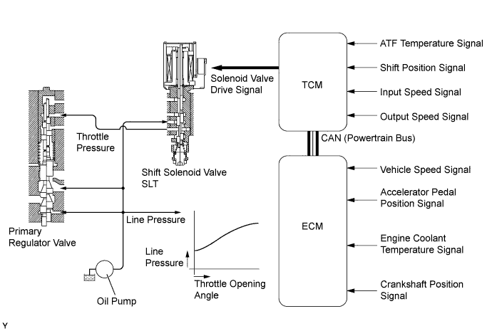
Line Pressure Control
-
In order to obtain a predetermined line pressure characteristic in accordance with each sensor signal, the TCM activates the shift solenoid valve SLT to regulate the throttle pressure.
-
This makes it possible for the primary regulator valve to precisely and minutely control the line pressure in accordance with the engine output, thus providing smoother shift characteristics.
-
-
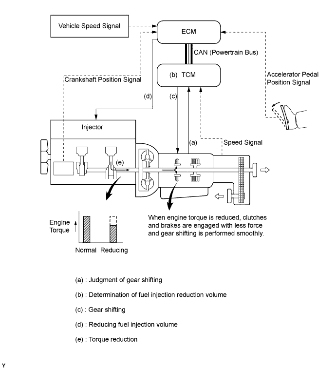
Engine Torque Control
-
Engagement of the clutches and brakes of the planetary gear unit in the transmission is controlled smoothly by momentarily reducing the fuel injection volume when gears are shifted up or down in the transmission. When the TCM judges a gear shift timing in accordance with signals, it activates the shift solenoid valves to perform gear shifting. When the gear shifting starts, the ECM reduces the fuel injection volume to reduce the engine torque. As a result, engagement force of the clutches and brakes of the planetary gear units is weakened and the gear change is performed smoothly.
-
-
Lock-up Timing Control
-
The TCM operates the lock-up timing control in order to improve the fuel consumption performance in the top gear when the shift lever is in D or 3.
Lock-up Timing Control Operation Gear Shift Lever Position D 3 1st X X 2nd X X 3rd X ○ 4th ○ - Tech Tips
○: Operates
X: Does not operate
-
-
-
FUNCTION
-
Shift Lock System
-
The shift lock system prevents the shift lever from being moved to any position other than P, unless the ignition switch is ON and the brake pedal is depressed. This prevents the vehicle from starting off suddenly.
-
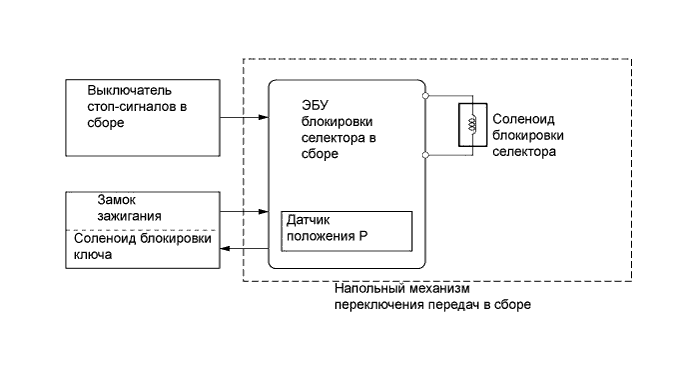
The shift lock system is controlled by the shift lock control ECU sub-assembly and it has a shift lock function and key interlock function.
-
The shift lock control ECU sub-assembly has a built-in P detection switch to detect the shift lever position, and receives input signals from the stop light switch assembly and ignition switch. Upon receiving these signals, the shift lock control ECU sub-assembly turns on the shift lock solenoid and the key interlock solenoid in order to release the shift lock and key interlock.
-
The key interlock function prevents the key from being pulled out after the ignition switch has been turned off, unless the shift lever has been moved to P. Thus, the driver is urged to park the vehicle with the shift lever in P.
-
A shift lock release button, which manually overrides the shift lock mechanism, is used.
-
-
-
CONSTRUCTION
-
Torque Converter Assembly
-
A compact, lightweight and high-capacity torque converter assembly is used. The torque converter supports lock-up clutch control, thus improving fuel economy.
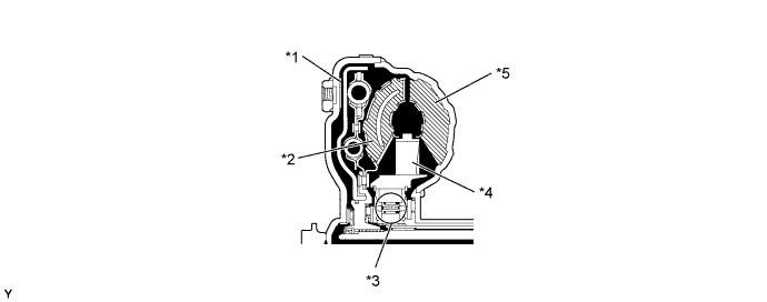
Text in Illustration *1 Lock-up Clutch *2 Turbine Runner *3 1-way Clutch *4 Stator *5 Pump Impeller - -
-
-
Oil Pump Assembly
-
The oil pump is operated by the torque converter assembly. It lubricates the planetary gear units and supplies operating fluid pressure for hydraulic control. The front oil pump drive gear is continually driven by the engine via the pump impeller. The pump has sufficient capacity to supply the necessary fluid pressure throughout all speed ranges, as well as in reverse.
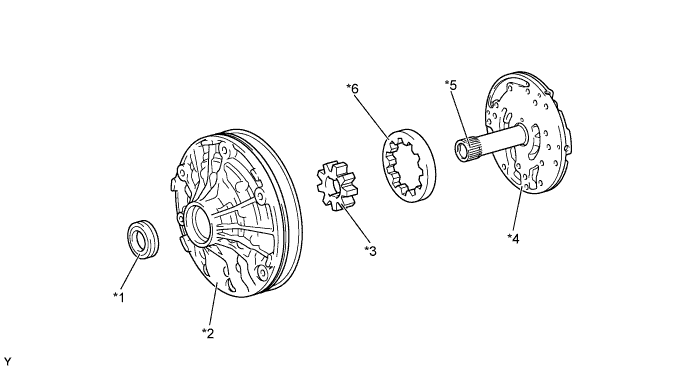
Text in Illustration *1 Oil Seal *2 Front Oil Pump Body Sub-assembly *3 Front Oil Pump Drive Gear *4 Oil Pump Cover *5 Stator Shaft Assembly *6 Front Oil Pump Driven Gear
-
-
Planetary Gear Unit
-
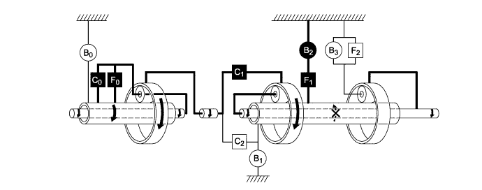
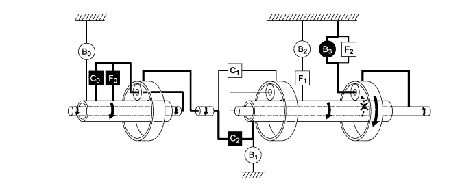
The gear train consists of three multi-plate clutches, three multi-plate brakes, a single band type brake, three 1-way clutches, and three sets of planetary gears each consisting of a sun gear, a pinion gear and a ring gear.
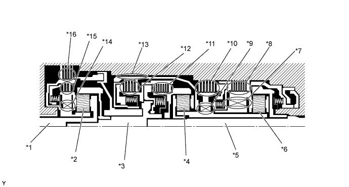
Text in Illustration *1 Overdrive Input Shaft *2 Overdrive Planetary Gear Assembly *3 Input Shaft *4 Front Planetary Gear Assembly *5 Output Shaft *6 Rear Planetary Gear Assembly *7 No. 2 1-way Clutch (F2)
*8 1st and Reverse Brake (B3)
*9 1-way Clutch Assembly (F1)
*10 2nd Brake (B2)
*11 Forward Clutch (C1)
*12 Direct Clutch (C2)
*13 2nd Coast Brake (B1)
*14 Overdrive 1-way Clutch (F0)
*15 Overdrive Direct Clutch (C0)
*16 Overdrive Brake (B0)
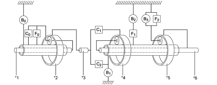
Text in Illustration *1 Overdrive Input Shaft *2 Overdrive Planetary Gear Assembly *3 Input Shaft *4 Front Planetary Gear Assembly *5 Rear Planetary Gear Assembly *6 Output Shaft
-
-
Transmission Valve Body Assembly
-
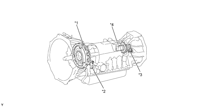
The transmission valve body assembly consists of upper and lower valve bodies and 4 shift solenoid valves.
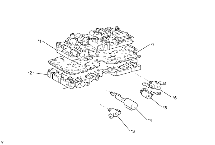
Text in Illustration *1 Upper Valve Body *2 Lower Valve Body *3 Shift Solenoid Valve SL *4 Shift Solenoid Valve SLT *5 Shift Solenoid Valve S2 *6 Shift Solenoid Valve S1 *7 Plate - - 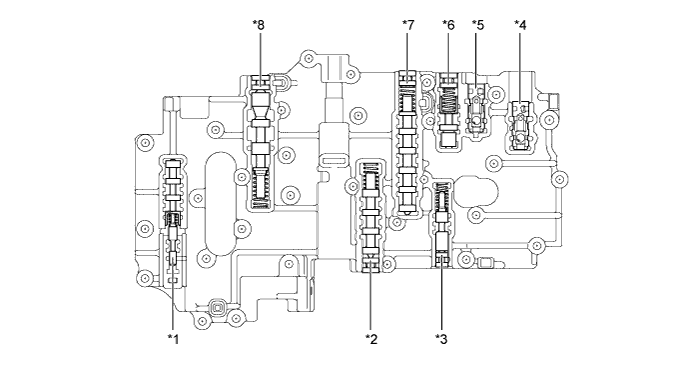
Text in Illustration (Upper Valve Body) *1 Lock-up Relay Valve *2 3-4 Shift Valve *3 2nd Coast Modulator Valve *4 B3Check Valve
*5 C2Check Valve
*6 Reverse Control Valve *7 2-3 Shift Valve *8 Secondary Regulator Valve 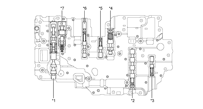
Text in Illustration (Lower Valve Body) *1 Primary Regulator Valve *2 1-2 Shift Valve *3 Low Coast Modulator Valve *4 Accumulator Control Valve *5 Solenoid Modulator Valve *6 Cut Back Valve *7 Lock-up Control Valve - -
-
-
Shift Solenoid Valves S1 and S2
-
The shift solenoid valves S1 and S2 are 2-way solenoid valves.
-
A filter is provided at the tip of each solenoid valve to further improve operational reliability.

Text in Illustration (Shift Solenoid Valves S1 and S2) *1 Filter - - 
Line Pressure 
Control Pressure Function of Shift Solenoid Valves S1 and S2 Shift Solenoid Valve Function S1 Switches the 2-3 shift valve. S2 Switches the 1-2 shift valve and the 3-4 shift valve.
-
-
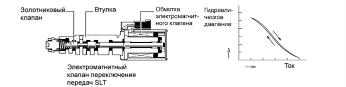
Shift Solenoid Valves SLT and SL
-
In order to provide a hydraulic pressure that is proportional to the current that flows to the solenoid coil, the shift solenoid valve SLT linearly controls the line pressure based on the signals it receives from the TCM.
-
The shift solenoid valve SL is a 2-way solenoid valve.
-
A filter is provided at the tip of the solenoid valve to further improve operational reliability.
Text in Illustration (Shift Solenoid Valve SL) *1 Filter - - Line Pressure Control Pressure Function of Shift Solenoid Valves SLT and SL Shift Solenoid Valve Function SLT
-
Line pressure control
-
Accumulator back pressure control
SL
-
Lock-up clutch pressure control
-
Accumulator back pressure control
-
-
-
ATF Temperature Sensor
-
An ATF temperature sensor, which is provided on the oil outlet, detects the ATF oil temperature necessary for shifting and for various controls and sends the information to the TCM.
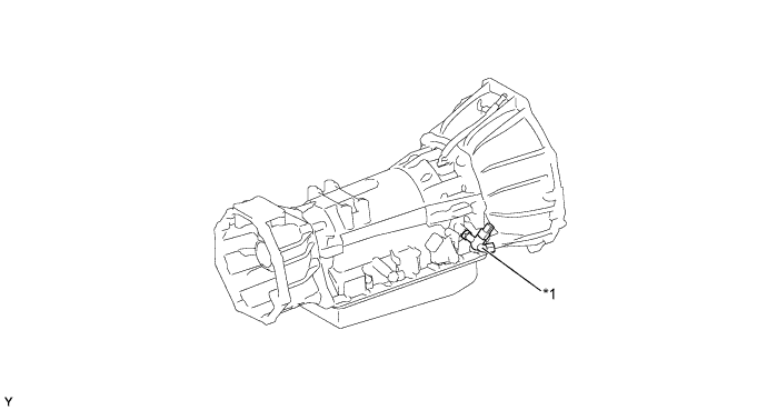
Text in Illustration *1 ATF Temperature Sensor - -
-
-
Speed Sensors
-
This automatic transmission uses an input speed sensor (for NCO signal) and an output speed sensor (for SP2 signal). Thus, the TCM can detect the timing of the shifting of the gears and appropriately control the engine torque and hydraulic pressure in response to various conditions.
-
These speed sensors are the pick-up coil type.
-
The input speed sensor detects the input speed of the transmission. The overdrive direct clutch drum is used as the timing rotor for this sensor.
-
The output speed sensor detects the speed of the output shaft.
Text in Illustration *1 Overdrive Direct Clutch Drum *2 Input Speed Sensor *3 Output Speed Sensor *4 Output Shaft
-
-
Park/Neutral Position Switch Assembly and Transmission Control Switch
-
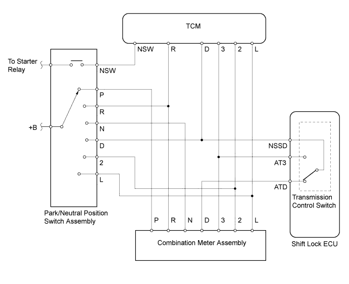
The TCM uses the park/neutral position switch assembly and the transmission control switch to detect the shift lever position.
-
The park/neutral position switch assembly sends the R, D, 2, L and NSW signals to the TCM. It also sends signals for the shift position indicator "P, R, N, 2 and L" in the combination meter assembly.
-
The transmission control switch is located in the shift lock control ECU sub-assembly. This switch sends the 3 signal to the TCM. It also sends a signal for the shift position indicator "D and 3" in the combination meter assembly.
-
-
Shift Control Mechanism
-
A gate type shift lever that uses a transmission control cable is used.
-
The shift control mechanism consists of a transmission floor shift assembly and a transmission control cable assembly.
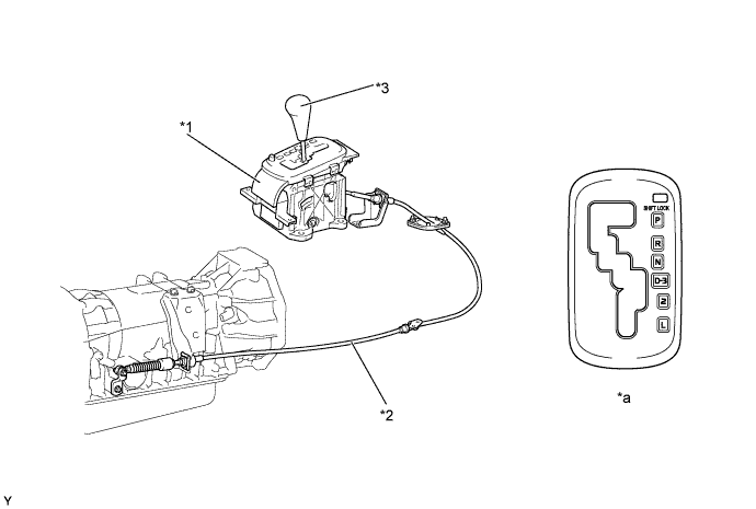
Text in Illustration *1 Transmission Floor Shift Assembly *2 Transmission Control Cable Assembly *3 Shift Lever Knob - - *a Shift Pattern - -
-
-
-
OPERATION
-
Transmission Power Flow
Operating Condition Shift Lever Position and Gear Range Gear Position Shift Solenoid Valve Clutch Brake 1-way Clutch S1 S2 C0
C1
C2
B0
B1
B2
B3
F0
F1
F2
P Park On Off ○ - - - - - - - - - R Reverse On Off ○ - ○ - - - ○ ○ - - N Neutral On Off ○ - - - - - - - - - D 1st On Off ○ ○ - - - - - ○ - ○ 2nd On On ○ ○ - - - ○ - ○ ○ - 3rd Off On ○ ○ ○ - - ○ - ○ - - 4th Off Off - ○ ○ ○ - ○ - - - - 3 1st On Off ○ ○ - - - - - ○ - ○ 2nd On On ○ ○ - - - ○ - ○ ○ - 3rd Off On ○ ○ ○ - - ○ - ○ - - 2 1st On Off ○ ○ - - - - - ○ - ○ 2nd* On On ○ ○ - - (○) ○ - ○ ○ - L 1st* On Off ○ ○ - - - - (○) ○ - ○ Tech Tips
○: Operates
(○): Operates during engine braking
-: Does not operate
*: Engine braking occurs
-
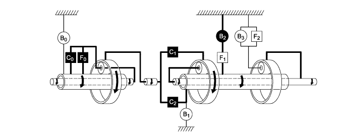
1st Gear (Shift Lever in D, 3 or 2)

Text in Illustration 
Operates - - -
2nd Gear (Shift Lever in D or 3)
Text in Illustration Operates - - -
3rd Gear (Shift Lever in D or 3)
Text in Illustration Operates - - -
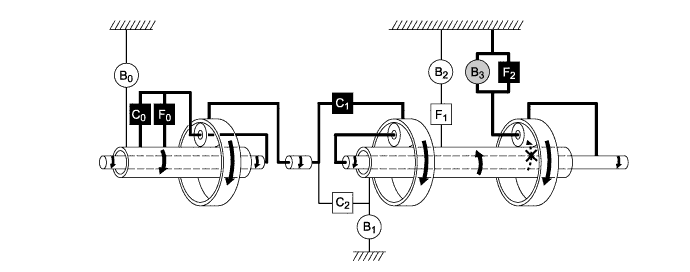
4th Gear (Shift Lever in D)
Text in Illustration Operates - - -
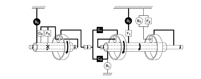
Engine Braking in 1st Gear (Shift Lever in L)
Text in Illustration Operates 
Operates during Engine Braking -
Engine Braking in 2nd Gear (Shift Lever in 2 or L)
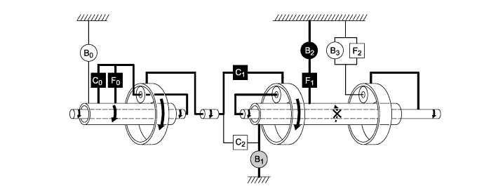
Text in Illustration Operates Operates during Engine Braking -
Reverse Gear (Shift Lever in R)
Text in Illustration Operates - -
-
-
-
FAIL-SAFE
-
The fail-safe function minimizes the loss of operability when an abnormality occurs in a sensor or a solenoid.
Fail-safe Control List Malfunction Part Function Output Speed Sensor (SP2) During an output speed sensor malfunction, shift control is effected through the input speed sensor signal (NCO) or engine speed signal (NE). ATF Temperature Sensor During a malfunction of the ATF temperature sensor, the system effects control by fixing the ATF temperature at 80°C (176°F). Shift Solenoid Valve S1/S2 The current to the failed shift solenoid valve is cut off and control is effected by operating the other solenoid valves with normal operation. Shift Solenoid Valve SLT During a shift solenoid valve SLT malfunction, the current to the shift solenoid valve is stopped. This stops line pressure control, thus increasing shift shock. However, shifting is effected through normal clutch pressure control. Shift Solenoid Valve SL During a shift solenoid valve SL malfunction, the current to the shift solenoid valve is stopped. This stops lock-up control, thus decreasing fuel economy.
-
-
DIAGNOSIS
-
When the ECM detects a malfunction, it makes a diagnosis and memorizes the failed section. Furthermore, the ECM illuminates or blinks the MIL in the combination meter assembly to inform the driver.
-
The ECM will also store the Diagnostic Trouble Codes (DTCs) of the malfunctions.
-
The DTCs can be read by connecting an intelligent tester II to the DLC3.
-
For details, refer to the corresponding Repair Manual for this model.
-