POWER BACK DOOR SYSTEM TERMINALS OF ECU
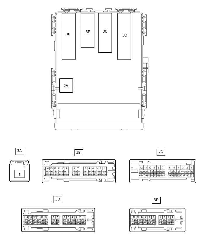
CHECK MULTIPLEX NETWORK DOOR ECU
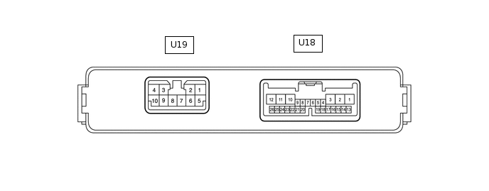
Disconnect the U18 and U19 multiplex network door ECU connectors.
Measure the voltage and resistance according to the value(s) in the table below.
Terminal No. (Symbol)
Wiring Color
Terminal Description
Condition
Specified Condition
U18-1 (ECUB) - Body ground
W - Body ground
Battery power supply
Always
11 to 14 V
U18-7 (IG) - Body ground
W - Body ground
IG power supply
Ignition switch ON
11 to 14 V
Ignition switch off
Below 1 V
U19-7 (GND) - Body ground
W-B - Body ground
Body ground
Always
Below 1 Ω
U19-8 (B) - Body ground
W - Body ground
Battery power supply
Always
11 to 14 V
Reconnect the U18 and U19 multiplex network door ECU connectors.
Measure the voltage and waveform according to the value(s) in the table below.
Terminal No. (Symbol)
Wiring Color
Terminal Description
Condition
Specified Condition
U18-2 (DSG2) - Body ground
P - Body ground
Power back door unit assembly set RH (door sensor) ground
Always
Below 1 V
U18-3 (DSV2) - Body ground
G - Body ground
Power back door unit assembly set RH (door sensor) power supply
Always
7 V or higher
U18-5 (BZR+) - Body ground
V - Body ground
Wireless door lock buzzer signal
Power back door warning buzzer sounding
Pulse generation
Power back door warning buzzer not sounding
Below 1 V
U18-6 (BDDN) - Body ground
LG - Body ground
Door control switch signal
Door control switch on
Below 1 V
Door control switch off
Pulse generation
U18-11 (DSG) - Body ground
P - Body ground
Power back door unit assembly set LH (door sensor) ground
Always
Below 1 V
U18-12 (DSV) - Body ground
G - Body ground
Power back door unit assembly set LH (door sensor) power supply
Always
7 V or higher
U18-16 (OSR) - U18-17 (OSE)
SB - GR
Power back door sensor assembly RH signal
Power back door sensor assembly RH not pressed
4 to 6 V
Power back door sensor assembly RH pressed
Below 1 V
U18-18 (OSL) - U18-17 (OSE)
L - GR
Power back door sensor assembly LH signal
Power back door sensor assembly LH not pressed
4 to 6 V
Power back door sensor assembly LH pressed
Below 1 V
U18-20 (MSW) - Body ground
W - Body ground
Power back door main switch signal
Power back door main switch on
Below 1 V
Power back door main switch off
Pulse generation
U18-22 (DS2) - Body ground
R - Body ground
Power back door unit assembly set LH (door sensor) signal
Power back door not operating
7 V or higher
Power back door operating
Pulse generation
(See waveform 2)
U18-23 (DS1) - Body ground
L - Body ground
Power back door unit assembly set LH (door sensor) signal
Power back door not operating
7 V or higher
Power back door operating
Pulse generation
(See waveform 1)
U18-25 (DS22) - Body ground
R - Body ground
Power back door unit assembly set RH (door sensor) signal
Power back door not operating
7 V or higher
Power back door operating
Pulse generation
(See waveform 2)
U18-26 (DS12) - Body ground
L - Body ground
Power back door unit assembly set RH (door sensor) signal
Power back door not operating
7 V or higher
Power back door operating
Pulse generation
(See waveform 1)
U19-10 (DC+) - U19-9 (DC-)
B - R
Back door lock assembly (back door lock motor) circuit
Back door lock motor operating
11 to 14 V
-
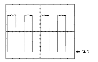
Using an oscilloscope, check waveform 1.
Table 1. Waveform 1 (Reference) Item
Condition
Tester connection
U18-23 (DS1) - Body ground
U18-26 (DS12) - Body ground
Tool setting
2 V/DIV., 2 ms./DIV.
Vehicle condition
Power back door operating
Tip:The period changes in accordance to the speed at which the power back door is opened and closed.
-
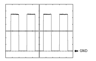
Using an oscilloscope, check waveform 2.
Table 2. Waveform 2 (Reference) Item
Condition
Tester connection
U18-22 (DS2) - Body ground
U18-25 (DS22) - Body ground
Tool setting
2 V/DIV., 2 ms./DIV.
Vehicle condition
Power back door operating
Tip:The period changes in accordance to the speed at which the power back door is opened and closed.
-
CHECK CERTIFICATION ECU (SMART KEY ECU ASSEMBLY) (w/ Entry and Start System)
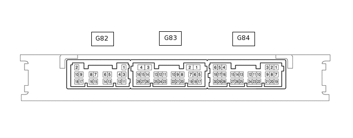
Disconnect the G82 and G84 certification ECU (smart key ECU assembly) connectors.
Measure the voltage and resistance according to the value(s) in the table below.
Terminal No. (Symbol)
Wiring Color
Terminal Description
Condition
Specified Condition
G82-2 (+B) - Body ground
W - Body ground
Battery power supply
Always
11 to 14 V
G82-10 (CUTB) - Body ground
P - Body ground
Battery power supply
Always
11 to 14 V
G84-5 (IG) - Body ground
LG - Body ground
IG power supply
Ignition switch ON
11 to 14 V
Ignition switch off
Below 1 V
G82-11 (E) - Body ground
BR - Body ground
Body ground
Always
Below 1 Ω
Reconnect the G82 and G84 certification ECU (smart key ECU assembly) connectors.
Measure the voltage according to the value(s) in the table below.
Terminal No. (Symbol)
Wiring Color
Terminal Description
Condition
Specified Condition
G83-27 (TSW5) - Body ground
Y - Body ground
Back door opener switch assembly signal
Back door opener switch assembly off
Pulse generation
Back door opener switch assembly on
Below 1 V
CHECK MAIN BODY ECU (MULTIPLEX NETWORK BODY ECU) AND INSTRUMENT PANEL JUNCTION BLOCK ASSEMBLY
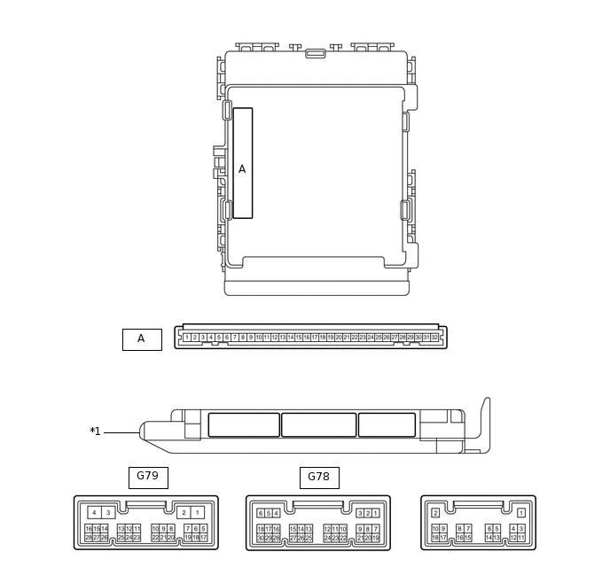
*1
Main Body ECU (Multiplex Network Body ECU)
-
-
Remove the main body ECU (multiplex network body ECU).
for LHD:Click here
for RHD:Click here
Connect the instrument panel junction block assembly connectors.
Measure the voltage and resistance according to the value(s) in the table below.
Terminal No. (Symbol)
Wiring Color
Terminal Description
Condition
Specified Condition
A-30 (BECU) -Body ground
None - Body ground
Battery power supply
Always
11 to 14 V
A-29 (ACC) -Body ground
None - Body ground
ACC power supply
Ignition switch ACC
11 to 14 V
Ignition switch off
Below 1 V
A-32 (IG) - Body ground
None - Body ground
IG power supply
Ignition switch ON
11 to 14 V
Ignition switch off
Below 1 V
A-11 (GND1) - Body ground
None - Body ground
Body ground
Always
Below 1 Ω
Install the main body ECU (multiplex network body ECU).
for LHD:Click here
for RHD:Click here
Measure the voltage according to the value(s) in the table below.
Terminal No. (Symbol)
Wiring Color
Terminal Description
Condition
Specified Condition
G78-23 (BDSU) - Body ground*
R - Body ground
Back door opener switch assembly signal
Back door opener switch assembly off
Pulse generation
Back door opener switch assembly on
Below 1 V
G79-27 (PBDS) - Body ground
R - Body ground
Back door control switch signal
Back door control switch off
Pulse generation
Back door control switch on
Below 1 V
*: w/o Entry and Start System