ECD SYSTEM, Diagnostic DTC:P2453
| DTC Code | DTC Name |
|---|---|
| P2453 | Diesel Particulate Filter Pressure Sensor "A" Circuit Range/Performance |
DESCRIPTION
For more information on the differential pressure sensor assembly and TOYOTA D-CAT*1, refer to thefollowing procedures (Click here).
If P2453 is present, refer to the DTC chart for TOYOTA D-CAT (Click here).
-
*1: Diesel Clean Advanced Technology
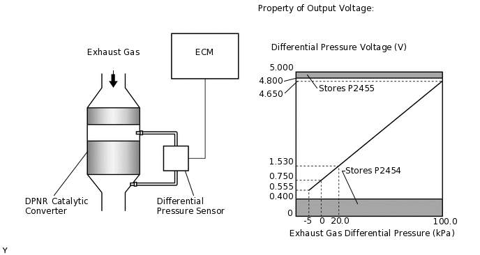
The two sensing chambers of the differential pressure sensor are mounted to monitor the pressure before and after the DPNR*2 catalytic converter. The sensor itself is not located on the engine assembly in order to reduce the influence of vibration. The sensor is a semiconductor-type that is not influenced by exhaust gases.
The ECM compares the exhaust gas pressure before and after the DPNR catalyst by monitoring the pressure using the upstream and downstream sensing chambers of the differential pressure sensor. If the difference between the pressure before and after the catalytic converter exceeds a predetermined level, the ECM judges that the catalytic converter is clogged with particulate matter (PM). When the ECM judges that a partially clogged condition exists, the ECM begins to perform PM forced regeneration.
*2: Diesel Particulate-NOx Reduction system
If the vacuum hoses of the differential pressure sensor are incorrectly connected (crossed), the ECM interprets this as an abnormal pressure difference, DTC P2453 (Diesel Particulate Filter Pressure Sensor "A" Circuit Range/Performance) is stored and the MIL illuminates.
DTC No. |
Detection Item |
DTC Detection Condition |
Trouble Area |
MIL |
Memory |
|---|---|---|---|---|---|
P2453 |
Diesel Particulate Filter Pressure Sensor "A" Circuit Range/Performance |
When the output voltage from the differential pressure sensor output voltage is reversal of positive and negative pressure (and vice versa). (1 trip detection logic) |
|
Comes on |
DTC stored |
DTC No. |
Data List |
|---|---|
P2453 |
DPF Differential Pressure |
DTC P2454 (Diesel Particulate Filter Pressure Sensor "A" Circuit Low) and/or DTC P2455 (Diesel Particulate Filter Pressure Sensor "A" Circuit High) will be stored if there is an open or short malfunction in the differential pressure sensor circuit.
After confirming DTC P2453, check the differential pressure in "Powertrain / Engine / Data List / DPF Differential Pressure" using the GTS.
Condition |
Differential Pressure Output |
Sensor Condition |
|---|---|---|
Ignition switch ON |
Approximately 0 kPa |
Normal |
Always |
-5 kPa or less or higher than 99 kPa |
Open or short circuit |
4000 rpm (No engine load) |
Negative output |
Incorrect hose routing |
MONITOR DESCRIPTION
In order to detect abnormality in the differential pressure sensor, the ECM always monitors the output voltage from the sensor. When the sensor output voltage is a reversal of positive and negative pressure, the ECM interprets this as an incorrect vacuum hose arrangement of the sensor, or determines that the vacuum hoses are clogged, and illuminates the MIL.
CONFIRMATION DRIVING PATTERN
DTC No. |
DTC Detection Drive Pattern |
|---|---|
P2453 |
Engine is running at 4000 rpm with no load for 10 seconds or more. |
CAUTION / NOTICE / HINT
After replacing the ECM, the new ECM needs registration (Click here) and initialization (Click here).
PROCEDURE
CHECK OTHER DTC OUTPUT (IN ADDITION TO DTC P2453)
Connect the GTS to the DLC3.
Turn the ignition switch to ON and turn the GTS
Enter the following menus: Powertrain / Engine / Trouble Codes.
Powertrain > Engine > Trouble Codes
Read the DTCs.
Result
Proceed to
DTC P2453 is output
DTC P2453 and other DTCs are output
Tip:If any DTCs other than P2453 are output, troubleshoot those DTCs first.
CHECK CONNECTION OF VACUUM HOSE (DIFFERENTIAL PRESSURE SENSOR - VACUUM TRANSMITTING PIPE)
Check if the vacuum hose routing between the differential pressure sensor and vacuum transmitting pipe is correct.
Check that there is no exhaust gas leakage between the differential pressure sensor and vacuum transmitting pipe.
Result
Proceed to
OK
NG
NG CORRECT TO NORMAL CONNECTIONClick here
CHECK BLOCKAGE OF VACUUM HOSE AND TRANSMITTING PIPE
CAUTION:Be careful of being burned by exhaust gases during the following inspection.
Disconnect the vacuum hoses (both upstream and downstream) from the differential pressure sensor.
Start the engine.
Check if there are exhaust gas pulsations from both vacuum hoses during idling.
OK
Exhaust gas pulsation exists.
Result
Proceed to
OK
NG
NG REPLACE CLOGGED PARTSClick here
READ VALUE USING GTS (DPF DIFFERENTIAL PRESSURE)
Connect the GTS to the DLC3.
Turn the ignition switch to ON and turn the GTS on.
Enter the following menus: Powertrain / Engine / Data List / DPF Differential Pressure.
Powertrain > Engine > Data List
Tester Display
DPF Differential Pressure
Check that the differential pressure is as specified below.
Table 3. Result Condition
Differential Pressure Output
Sensor Condition
Ignition switch ON
Approximately 0 kPa
Normal
Result
Proceed to
OK
NG
OK CONFIRM WHETHER MALFUNCTION HAS BEEN SUCCESSFULLY REPAIREDClick here
REPLACE DIFFERENTIAL PRESSURE SENSOR ASSEMBLY
Replace the differential pressure sensor assembly.
Result
Proceed to
NEXT
CONFIRM WHETHER MALFUNCTION HAS BEEN SUCCESSFULLY REPAIRED
Connect the GTS to the DLC3.
Turn the ignition switch to ON and turn the GTS on.
Clear the DTCs.
Powertrain > Engine > Clear DTCs
Turn the ignition switch off for 30 seconds or more.
Turn the ignition switch to ON and turn the GTS on.
Enter the following menus: Powertrain / Engine / Data List / DPF Differential Pressure.
Powertrain > Engine > Data List
Tester Display
DPF Differential Pressure
Check that the differential pressure is as specified below.
Tip:As long as the pipe connections are correct, the displayed pressure will not be vacuum pressure.
For reference result of real-vehicle check is as shown in the table below:
Condition
DPF Differential Pressure
2500 rpm without load
1.30 kPa
Start the engine.
Engine is running at 4000 rpm with no load for 10 seconds or more.
Enter the following menus: Powertrain / Engine / Trouble Codes.
Powertrain > Engine > Trouble Codes
Confirm that the DTC is not output again.
Tip:Perform the following procedure using the GTS to determine whether or not the DTC judgment has been carried out.
Enter the following menus: Powertrain / Engine / Utility / All Readiness.
Powertrain > Engine > Utility
Tester Display
All Readiness
Input DTC P2453.
Check that STATUS is NORMAL. If STATUS is INCOMPLETE or N/A, run the engine at 4000 rpm with no load for 10 seconds or more.
Result
Proceed to
NEXT
NEXT END
REPLACE CLOGGED PARTS
Result
Proceed to
NEXT
NEXT CONFIRM WHETHER MALFUNCTION HAS BEEN SUCCESSFULLY REPAIREDClick here
CORRECT TO NORMAL CONNECTION
Result
Proceed to
NEXT
NEXT CONFIRM WHETHER MALFUNCTION HAS BEEN SUCCESSFULLY REPAIREDClick here