SFI SYSTEM(w/o Canister Pump Module), Diagnostic DTC:P16B318, P16B319
| DTC Code | DTC Name |
|---|---|
| P16B318 | Multi Flow Control Valve Motor Circuit Current Below Threshold |
| P16B319 | Multi Flow Control Valve Motor Circuit Current Above Threshold |
DESCRIPTION
Refer to DTC P16B871.
| DTC No. | Detection Item | DTC Detection Condition | Trouble Area | MIL | Memory | Note |
|---|---|---|---|---|---|---|
| P16B318 | Multi Flow Control Valve Motor Circuit Current Below Threshold | Both of the following conditions are met for 2 seconds or more (1 trip detection logic):
|
|
Comes on | DTC stored | SAE: P16B1 |
| P16B319 | Multi Flow Control Valve Motor Circuit Current Above Threshold | A motor driver IC high current limiter monitor input malfunction is detected for 2 seconds or more (1 trip detection logic). |
|
Comes on | DTC stored | SAE: P16B2 |
MONITOR DESCRIPTION
This DTC is designed to detect an open or short in the water control valve DC motor circuit. If the water control valve DC motor current is excessively high or low, the ECM will store this DTC.
MONITOR STRATEGY
| Required Sensors/Components (Main) | Ball valve actuator (water control valve) |
| Frequency of Operation | Continuous |
CONFIRMATION DRIVING PATTERN
-
Connect the GTS to the DLC3.
-
Turn the engine switch on (IG).
-
Turn the GTS on.
-
Clear the DTCs (even if no DTCs are stored, perform the clear DTC procedure).
-
Turn the engine switch off and wait for at least 30 seconds.
-
Start the engine [A].
-
Idle the engine for 120 seconds or more.
-
Turn the engine switch off and wait for at least 30 seconds.
-
Turn the engine switch on (IG).
-
Turn the GTS on.
-
Enter the following menus: Powertrain / Engine / Trouble Codes [B].
-
Read the pending DTCs.
Tech Tips
-
If a pending DTC is output, the system is malfunctioning.
-
If a pending DTC is not output, perform the following procedure.
-
-
Enter the following menus: Powertrain / Engine / Utility / All Readiness.
-
Input the DTC: P16B318 or P16B319.
-
Check the DTC judgment result.
GTS Display Description NORMAL
-
DTC judgment completed
-
System normal
ABNORMAL
-
DTC judgment completed
-
System abnormal
INCOMPLETE
-
DTC judgment not completed
-
Perform driving pattern after confirming DTC enabling conditions
Tech Tips
-
If the judgment result is NORMAL, the system is normal.
-
If the judgment result is ABNORMAL, the system has a malfunction.
-
If the judgment result is INCOMPLETE, perform steps [A] through [B] again.
-
WIRING DIAGRAM
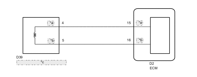
| *a | FCM+ |
| *b | FCM- |
| *c | DC motor (Water Control Valve) |
CAUTION / NOTICE / HINT
Tech Tips
Read Freeze Frame Data using the GTS. The ECM records vehicle and driving condition information as Freeze Frame Data the moment a DTC is stored. When troubleshooting, Freeze Frame Data can help determine if the vehicle was moving or stationary, if the engine was warmed up or not, if the air fuel ratio was lean or rich, and other data from the time the malfunction occurred.
PROCEDURE
-
INSPECT WATER CONTROL VALVE
-
Inspect the water control valve.
Result Proceed to OK NG
NG 
REPLACE WATER CONTROL VALVE Click here
OK 
-
-
CHECK HARNESS AND CONNECTOR (WATER CONTROL VALVE - ECM)
-
Disconnect the water control valve connector.
-
Disconnect the ECM connector.
-
Measure the resistance according to the value(s) in the table below.
Standard Resistance Tester Connection Condition Specified Condition D39-4 (FCM+) - D2-15 (FCM+) Always Below 1 Ω D39-5 (FCM-) - D2-16 (FCM-) Always Below 1 Ω D39-4 (FCM+) or D2-15 (FCM+) - Body ground and other terminals Always 10 kΩ or higher D39-5 (FCM-) or D2-16 (FCM-) - Body ground and other terminals Always 10 kΩ or higher Result Proceed to OK NG
NG
REPAIR OR REPLACE HARNESS OR CONNECTOR
OK
-
-
INSPECT ECM (INTERNAL CIRCUIT)
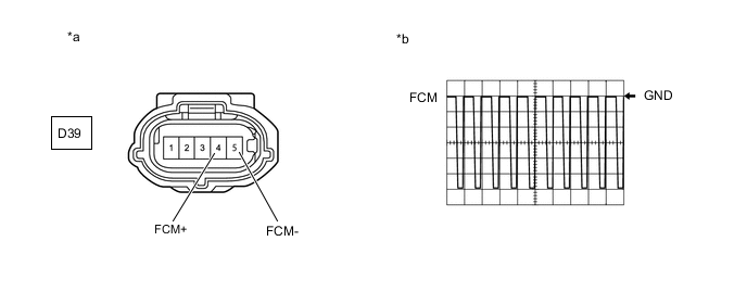
*a Front view of wire harness connector
(to Water Control Valve)
*b Waveform of FCM+ terminal and FCM- terminal during fail-safe
-
Disconnect the water control valve connector.
-
Inspect the ECM using an oscilloscope.
-
Turn the engine switch on (IG).
-
While the engine switch on (IG), check the waveform the terminals of the water control valve connector.
ECM Terminal Name D39-4 (FCM+) - D39-5 (FCM-) Tester Range 2 V/DIV., 1 ms./DIV. Condition Engine switch on (IG) -
While the engine switch is on (IG), check the waveform between the FCM+ terminal and FCM- terminal during fail-safe.
Standard 25% duty waveform is output Tech Tips
-
Check the operation circuit of the ECM by checking the waveform during fail-safe.
-
Because fail-safe is prohibited when the ambient temperature is 0°C (32°F) or less, work in a location where the ambient temperature is 5°C (41°F) or higher.
-
DTCs may be stored during this inspection. Check for DTCs and clear them using the GTS.
Result Proceed to OK NG -
OK
REPLACE WATER CONTROL VALVE Click here
NG
REPLACE ECM Click here
-