FRONT POWER SEAT CONTROL SYSTEM(w/ Memory) TERMINALS OF ECU
CHECK POSITION CONTROL ECU AND SWITCH ASSEMBLY (for LHD)
Disconnect the e18 and e6 position control ECU and switch assembly connectors.

Measure the voltage and resistance according to the value(s) in the table below.
Terminal Connection
Wiring Color
Terminal Description
Condition
Specified Condition
e18-2 (GND1) - Body ground
W-B - Body ground
Ground
Always
Below 1 Ω
e18-7 (+B1) - e18-2 (GND)
W - W-B
Battery supply
Always
11 to 14 V
e6-3 (IG) - e18-2 (GND)
R - W-B
IG power supply
Ignition switch off
Below 1 V
Ignition switch ON
11 to 14 V
e6-12 (SYSB) - e18-2 (GND)
P - W-B
System power supply
Always
11 to 14 V
Reconnect the e18 and e6 position control ECU and switch assembly connectors.
Measure the voltage and resistance according to the value(s) in the table below.
Terminal Connection
Wiring Color
Terminal Description
Condition
Specified Condition
e18-6 (+B2) - e18-1 (GND2)
SB - W-B
Lumbar support adjuster power source
Always
11 to 14 V
e18-1 (GND2) - Body ground
W-B - Body ground
Lumbar support adjuster ground
Always
Below 1 Ω
e18-3 (SLD+) - e18-2 (GND1)
L - W-B
Slide motor signal (forward)
Slide switch off
Below 1 V
Slide switch on (Forward)
11 to 14 V
e18-4 (SLD-) - e18-2 (GND1)
GR - W-B
Slide motor signal (rearward)
Slide switch off
Below 1 V
Slide switch on (Rearward)
11 to 14 V
e18-5 (FRV-) - e18-2 (GND1)
R - W-B
Front vertical motor signal (downward)
Front vertical switch off
Below 1 V
Front vertical switch on (Downward)
11 to 14 V
e18-8 (FRV+) - e18-2 (GND1)
B - W-B
Front vertical motor signal (upward)
Front vertical switch off
Below 1 V
Front vertical switch on (Upward)
11 to 14 V
e18-9 (RCL+) - e18-2 (GND1)
P - W-B
Reclining motor signal (forward)
Reclining switch off
Below 1 V
Reclining switch on (Forward)
11 to 14 V
e18-11 (RCL-) - e18-2 (GND1)
LG - W-B
Reclining motor signal (rearward)
Reclining switch off
Below 1 V
Reclining switch on (Rearward)
11 to 14 V
e18-10 (LFT+) - e18-2 (GND1)
V - W-B
Lifter motor signal (upward)
Lifter switch off
Below 1 V
Lifter switch on (Upward)
11 to 14 V
e18-12 (LFT-) - e18-2 (GND1)
G - W-B
Lifter motor signal (downward)
Lifter switch off
Below 1 V
Lifter switch on (Downward)
11 to 14 V
CHECK POSITION CONTROL ECU AND SWITCH ASSEMBLY (for RHD)
Disconnect the d27 and d28 position control ECU and switch assembly connectors.

Measure the voltage and resistance according to the value(s) in the table below.
Terminal Connection
Wiring Color
Terminal Description
Condition
Specified Condition
d27-2 (GND1) - Body ground
W-B - Body ground
Ground
Always
Below 1 Ω
d27-7 (+B1) - d27-2 (GND1)
W - W-B
Battery supply
Always
11 to 14 V
d28-3 (IG) - d27-2 (GND)
R - W-B
IG power supply
Ignition switch off
Below 1 V
Ignition switch ON
11 to 14 V
d28-12 (SYSB) - d27-2 (GND)
P - W-B
System power supply
Always
11 to 14 V
Reconnect the d27 and d28 position control ECU and switch assembly connectors.
Measure the voltage and resistance according to the value(s) in the table below.
Terminal Connection
Wiring Color
Terminal Description
Condition
Specified Condition
d27-6 (+B2) - d27-1 (GND2)
SB - W-B
Lumbar support adjuster power source
Always
11 to 14 V
d27-1 (GND2) - Body ground
W-B - Body ground
Lumbar support adjuster ground
Always
Below 1 Ω
d27-3 (SLD+) - d27-2 (GND1)
L - W-B
Slide motor signal (forward)
Slide switch off
Below 1 V
Slide switch on (Forward)
11 to 14 V
d27-4 (SLD-) - d27-2 (GND1)
GR - W-B
Slide motor signal (rearward)
Slide switch off
Below 1 V
Slide switch on (Rearward)
11 to 14 V
d27-5 (FRV-) - d27-2 (GND1)
R - W-B
Front vertical motor signal (downward)
Front vertical switch off
Below 1 V
Front vertical switch on (Downward)
11 to 14 V
d27-8 (FRV+) - d27-2 (GND1)
B - W-B
Front vertical motor signal (upward)
Front vertical switch off
Below 1 V
Front vertical switch on (Upward)
11 to 14 V
d27-9 (RCL+) - d27-2 (GND1)
P - W-B
Reclining motor signal (forward)
Reclining switch off
Below 1 V
Reclining switch on (Forward)
11 to 14 V
d27-11 (RCL-) - d27-2 (GND1)
LG - W-B
Reclining motor signal (rearward)
Reclining switch off
Below 1 V
Reclining switch on (Rearward)
11 to 14 V
d27-10 (LFT+) - d27-2 (GND1)
V - W-B
Lifter motor signal (upward)
Lifter switch off
Below 1 V
Lifter switch on (Upward)
11 to 14 V
d27-12 (LFT-) - d27-2 (GND1)
G - W-B
Lifter motor signal (downward)
Lifter switch off
Below 1 V
Lifter switch on (Downward)
11 to 14 V
CHECK MAIN BODY ECU (MULTIPLEX NETWORK BODY ECU) AND INSTRUMENT PANEL JUNCTION BLOCK ASSEMBLY
Remove the main body ECU (multiplex network body ECU).
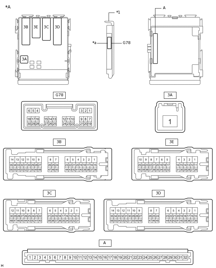
*A
Main Body ECU (Multiplex Network Body ECU) with 1 Connector
-
-
*1
Main Body ECU (Multiplex Network Body ECU)
-
-
*a
1 Connector
-
-
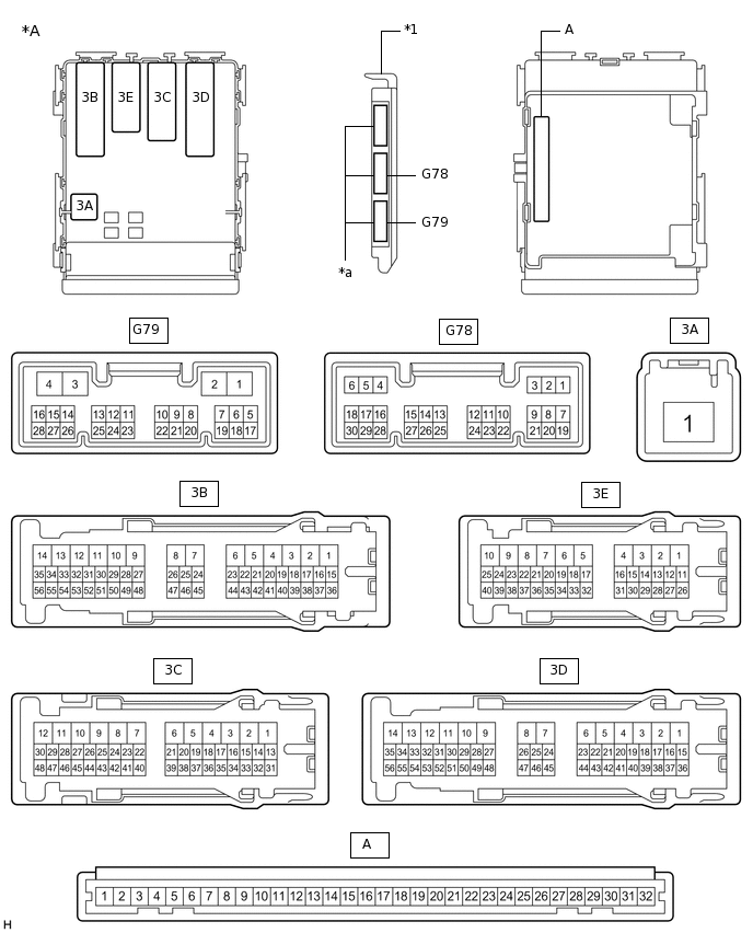
*A
Main Body ECU (Multiplex Network Body ECU) with 3 Connectors
-
-
*1
Main Body ECU (Multiplex Network Body ECU)
-
-
*a
3 Connectors
-
-
Measure the voltage and resistance according to the value(s) in the table below.
Terminal Connection
Wiring Color
Terminal Description
Condition
Specified Condition
A-30 (BECU) - Body ground
-
Battery power supply
Always
11 to 14 V
A-32 (IG) - Body ground
-
IG power supply
Ignition switch ON
11 to 14 V*1
10.5 to 14 V*2
A-32 (IG) - Body ground
-
IG power supply
Ignition switch off
Below 1 V
A-29 (ACC) - Body ground
-
ACC power supply
Ignition switch ACC
11 to 14 V
A-29 (ACC) - Body ground
-
ACC power supply
Ignition switch off
Below 1 V
A-11 (GND1) - Body ground
-
Ground
Always
Below 1 Ω
*1: w/o Stop and Start System
*2: w/ Stop and Start System
Install the main body ECU (multiplex network body ECU).
Measure the voltage and check for pulses according to the value(s) in the table below.
Tester Connection
Wiring Color
Terminal Description
Condition
Specified Condition
G78-19 (FRCY) - Body ground*1
L - Body ground
Front door courtesy light switch RH input
Front door RH open
Below 1 V
Front door RH closed
Pulse generation
3E-40 (FLCY) - Body ground*2
W - Body ground
Front door courtesy light switch LH input
Front door LH open
Below 1 V
Front door LH closed
Pulse generation
*1: for RHD
*2: for LHD