LANE DEPARTURE ALERT SWITCH(for RHD) INSPECTION
PROCEDURE
INSPECT LANE-KEEPING ASSIST MAIN SWITCH (LANE DEPARTURE ALERT SWITCH)
-
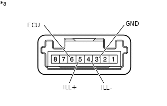
*a
Component without harness connected
(Lane-keeping Assist Main Switch (lane departure alert switch))
Measure the resistance according to the value(s) in the table below.
Standard Resistance
Tester Connection
Condition
Specified Condition
3(GND) - 6(ECU)
Lane-keeping assist main switch (lane departure alert switch) pushed
Below 1 Ω
3(GND) - 6(ECU)
Lane-keeping assist main switch (lane departure alert switch) not pushed
10 kΩ or higher
If the result is not as specified, replace the lane-keeping assist main switch (lane departure alert switch).
Inspect the illumination operation.
Apply battery voltage to the lane-keeping assist main switch connector, and check that the lane-keeping assist main switch (lane departure alert switch) illuminates.
OK
Measurement Condition
Specified Condition
Battery positive (+) → Terminal 5(ILL+)
Battery negative (-) → Terminal 4(ILL-)
Illuminates
If the result is not as specified, replace the lane-keeping assist main switch (lane departure alert switch).
-