SPEED LIMITER SYSTEM Speed Limiter System does not Operate
| DTC Code | DTC Name |
|---|---|
| Speed Limiter System does not Operate |
DESCRIPTION
When the speed limiter system is turned on using the adjustable speed limiter switch (cruise control main switch), the ECM illuminates the speed limiter indicator and activates the speed limiter system. Each function of the speed limiter system can be activated by operating the adjustable speed limiter switch (cruise control main switch).
WIRING DIAGRAM
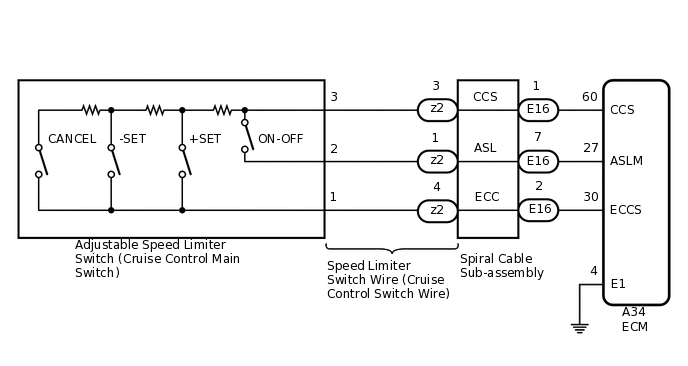
PROCEDURE
READ VALUE ON GTS
-
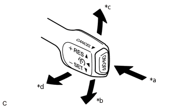
*a
ON-OFF
*b
- SET
*c
+ RES
*d
CANCEL
Connect the GTS to the DLC3.
Turn the ignition switch to ON.
Turn the GTS on.
Enter the following menus: Powertrain / Engine and ECT / Data List.
Check the Data List to confirm proper functioning of the adjustable speed limiter switch (cruise control main switch).
Powertrain > Engine and ECT > Data List
Tester Display
Measurement Item
Range
Normal Condition
Diagnostic Note
Cancel Switch
CANCEL switch signal
ON or OFF
ON: CANCEL switch operated
OFF: CANCEL switch released
-
SET/COAST Switch
- SET switch signal
ON or OFF
ON: - SET switch operated
OFF: - SET switch released
-
RES/ACC Switch
+ RES switch signal
ON or OFF
ON: + RES switch operated
OFF: + RES switch released
-
ASL Main Switch
Adjustable speed limiter switch (Cruise control main switch) (ON-OFF button) signal
ON or OFF
ON: Adjustable speed limiter switch (Cruise control main switch) (ON-OFF button) pushed and held
OFF: Adjustable speed limiter switch (Cruise control main switch) (ON-OFF button) released
-
OK
When the adjustable speed limiter switch (cruise control main switch) is operated, the display changes as shown above.
Result
Proceed to
OK
NG
-
INSPECT ADJUSTABLE SPEED LIMITER SWITCH (CRUISE CONTROL MAIN SWITCH)
Remove the adjustable speed limiter switch (cruise control main switch).
Measure the resistance according to the value(s) in the table below.
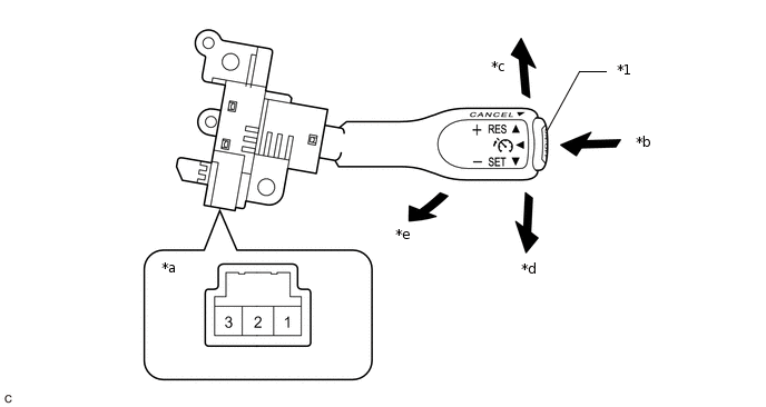
*1
Adjustable Speed Limiter Switch (Cruise Control Main Switch) (ON-OFF button)
-
-
*a
Component without harness connected
(Adjustable Speed Limiter Switch (Cruise Control Main Switch))
*b
ON-OFF
*c
+ RES
*d
- SET
*e
CANCEL
-
-
Standard Resistance
Tester Connection
Condition
Specified Condition
1 - 2
Adjustable speed limiter switch (Cruise control main switch) (ON-OFF button) released
1 MΩ or higher
1 - 2
Adjustable speed limiter switch (Cruise control main switch) (ON-OFF button) pushed
Below 2.5 Ω
1 - 3
+ RES switch operated
235 to 245 Ω
1 - 3
- SET switch operated
617 to 643 Ω
1 - 3
CANCEL switch operated
1509 to 1571 Ω
Result
Proceed to
OK
NG
CHECK SPEED LIMITER SWITCH WIRE (CRUISE CONTROL SWITCH WIRE)
-
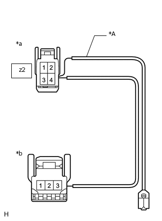
*A
w/ Steering Pad Switch Assembly
*a
Front view of wire harness connector
(to Spiral Cable Sub-assembly)
*b
Front view of wire harness connector
(to Adjustable Speed Limiter Switch (Cruise Control Main Switch))
Remove the speed limiter switch wire (cruise control switch wire).
Measure the resistance according to the value(s) in the table below.
Standard Resistance (Check for Open)
Tester Connection
Specified Condition
z2-1 - Adjustable speed limiter switch (Cruise control main switch) side connector terminal 2
Below 1 Ω
z2-3 - Adjustable speed limiter switch (Cruise control main switch) side connector terminal 3
Below 1 Ω
z2-4 - Adjustable speed limiter switch (Cruise control main switch) side connector terminal 1
Below 1 Ω
Result
Proceed to
OK
NG
NG REPLACE SPEED LIMITER SWITCH WIRE (CRUISE CONTROL SWITCH WIRE)
-
INSPECT SPIRAL CABLE SUB-ASSEMBLY
Inspect the spiral cable sub-assembly.
Result
Proceed to
OK
NG
CHECK HARNESS AND CONNECTOR (ECM - SPIRAL CABLE SUB-ASSEMBLY)
Disconnect the A34 ECM connector.
Disconnect the E16 spiral cable sub-assembly connector.
Measure the resistance according to the value(s) in the table below.
Standard Resistance
Tester Connection
Condition
Specified Condition
A34-60 (CCS) - E16-1 (CCS)
Always
Below 1 Ω
A34-27 (ASLM) - E16-7 (ASL)
Always
Below 1 Ω
A34-30 (ECCS) - E16-2 (ECC)
Always
Below 1 Ω
A34-60 (CCS) or E16-1 (CCS) - Body ground
Always
10 kΩ or higher
A34-27 (ASLM) or E16-7 (ASL) - Body ground
Always
10 kΩ or higher
A34-30 (ECCS) or E16-2 (ECC) - Body ground
Always
10 kΩ or higher
Result
Proceed to
OK
NG
NG REPAIR OR REPLACE HARNESS OR CONNECTOR (ECM - SPIRAL CABLE SUB-ASSEMBLY)
CHECK HARNESS AND CONNECTOR (ECM - BODY GROUND)
Disconnect the A34 ECM connector.
Measure the resistance according to the value(s) in the table below.
Standard Resistance
Tester Connection
Condition
Specified Condition
A34-4 (E1) - Body ground
Always
Below 1 Ω
Result
Proceed to
OK
NG
NG REPAIR OR REPLACE HARNESS OR CONNECTOR (ECM - BODY GROUND)