REAR SEAT ENTERTAINMENT SYSTEM Visual Mute Signal Circuit between Navigation ECU and Multi-display Controller
| DTC Code | DTC Name |
|---|---|
| Visual Mute Signal Circuit between Navigation ECU and Multi-display Controller |
DESCRIPTION
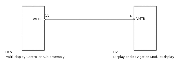
This is the visual mute signal circuit between the display and navigation module display and the multi-display controller sub-assembly.
WIRING DIAGRAM
PROCEDURE
CHECK DISPLAY AND NAVIGATION MODULE DISPLAY
-
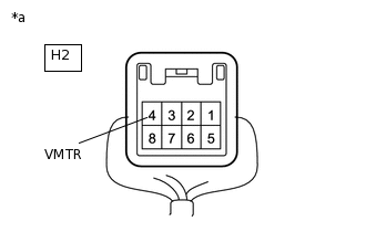
*a
Component with harness connected
(Display and Navigation Module Display)
Measure the voltage according to the value(s) in the table below.
Standard Voltage
Tester Connection
Condition
Specified Condition
H2-4 (VMTR) - Body ground
RSE playing → Source changed
Higher than 3.5 V → Below 1 V
Result
Result
OK
NG
-
CHECK HARNESS AND CONNECTOR (DISPLAY AND NAVIGATION MODULE DISPLAY - MULTI-DISPLAY CONTROLLER)
Disconnect the H2 display and navigation module display connector.
Disconnect the H16 multi-display controller sub-assembly connector.
Measure the resistance according to the value(s) in the table below.
Standard Resistance
Tester Connection
Condition
Specified Condition
H2-4 (VMTR) - H16-11 (VMTR)
Always
Below 1 Ω
H2-4 (VMTR) - Body ground
Always
10 kΩ or higher
Result
Result
OK
NG
NG REPAIR OR REPLACE HARNESS OR CONNECTOR
CHECK DISPLAY AND NAVIGATION MODULE DISPLAY
-
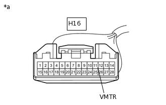
*a
Front view of wire harness connector
(to Multi-display Controller Sub-assembly)
Measure the voltage according to the value(s) in the table below.
Standard Voltage
Tester Connection
Condition
Specified Condition
H16-11 (VMTR) - Body ground
RSE playing → Source changed
Higher than 3.5 V → Below 1 V
Result
Result
OK
NG
-