OIL COOLER INSTALLATION
PROCEDURE
INSTALL OIL COOLER ASSEMBLY (w/ Air Cooled Transmission Oil Cooler)
Install the 2 oil cooler brackets with the 2 bolts.
5.5 N*m
56 kgf*cm
49 in.*lbf
-
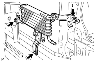
Attach the 2 claws of the oil cooler assembly to the hole of the radiator support and the center brace in that order to install the oil cooler assembly.
Install the 3 bolts and tighten the bolts in the order shown in the illustration.
5.5 N*m
56 kgf*cm
49 in.*lbf
INSTALL NO. 3 OIL COOLER TUBE SUB-ASSEMBLY (w/ Air Cooled Transmission Oil Cooler)
Pass the No. 3 oil cooler tube sub-assembly through the hole of the radiator support from the rear of the vehicle and install it to the oil cooler bracket with the bolt.
5.5 N*m
56 kgf*cm
49 in.*lbf
INSTALL NO. 5 OIL COOLER INLET HOSE AND NO. 5 OIL COOLER OUTLET HOSE (w/ Air Cooled Transmission Oil Cooler)
-
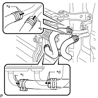
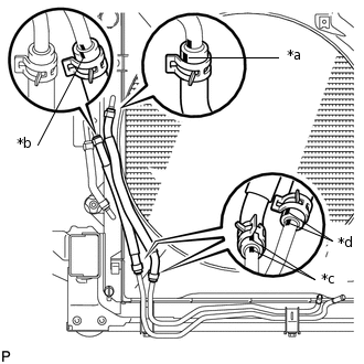
*a
Blue Paint Mark
*b
Pink Paint Mark
*c
Yellow Paint Mark
*d
White Paint Mark
Connect the No. 5 oil cooler inlet hose and No. 5 oil cooler outlet hose to the oil cooler assembly, and slide the clips to secure it.
Note:Make sure the pinching portion of each clip is facing the direction shown in the illustration and the paint marks are aligned as shown in the illustration.
Connect the 2 hoses to the No. 3 oil cooler tube sub-assembly to install them, and slide the clips to secure it.
Note:Make sure the pinching portion of each clip is facing the direction shown in the illustration and the paint marks are aligned as shown in the illustration.
-
INSTALL NO. 2 OIL COOLER TUBE SUB-ASSEMBLY
-
Install the No. 2 oil cooler tube sub-assembly with the 2 bolts.
14 N*m
143 kgf*cm
10 ft.*lbf
Note:Make sure the rotation stopper of the tube contacts the crossmember.
-
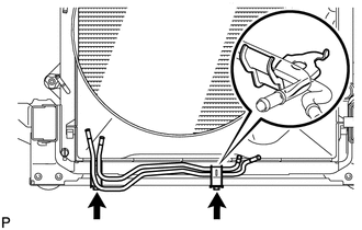
INSTALL NO. 6 OIL COOLER OUTLET HOSE (w/ Air Cooled Transmission Oil Cooler)
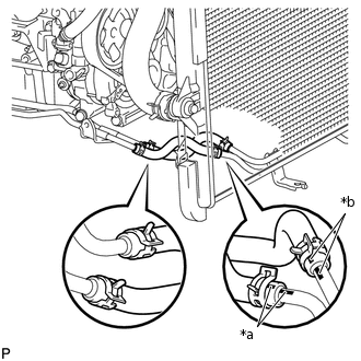
-
*a
Yellow Paint Mark
*b
White Paint Mark
Connect the No. 6 oil cooler outlet hose to the radiator and No. 3 oil cooler tube sub-assembly to install it, and slide the clips to secure it.
Note:When connecting the hose to the tube, support the tube by hand and be careful to prevent the tube from being deformed.
Make sure the paint mark and pinching portion of each clip are facing the directions shown in the illustration.
-
INSTALL NO. 4 OIL COOLER INLET HOSE AND NO. 4 OIL COOLER OUTLET HOSE (w/ Air Cooled Transmission Oil Cooler)
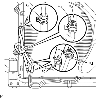
-
*a
Yellow Paint Mark
*b
White Paint Mark
*c
Pink Paint Mark
*d
Blue Paint Mark
Connect the No. 4 oil cooler inlet hose and No. 4 oil cooler outlet hose to the No. 2 oil cooler tube sub-assembly,and slide the clips to secure it.
Note:When connecting the hose to the tube, support the tube by hand and be careful to prevent the tube from being deformed.
Make sure the paint mark and pinching portion of each clip are facing the directions shown in the illustration.
Connect the No. 4 oil cooler inlet hose and No. 4 oil cooler outlet hose to the radiator and No. 3 oil cooler tube sub-assembly to install them, and slide the clips to secure it.
Note:When connecting the hose to the tube, support the tube by hand and be careful to prevent the tube from being deformed.
Make sure the paint mark and pinching portion of each clip are facing the directions shown in the illustration.
-
INSTALL OIL COOLER ACCESSORY ASSEMBLY (w/o Air Cooled Transmission Oil Cooler)
Connect the 2 oil cooler hoses to the No. 2 oil cooler tube sub-assembly, and slide the clips to secure it.
Note:When connecting the hose to the tube, support the tube by hand and be careful to prevent the tube from being deformed.
Make sure the paint mark and pinching portion of each clip are facing the directions shown in the illustration.
-
*a
Yellow Paint Mark
*b
White Paint Mark
*c
Pink Paint Mark
*d
Blue Paint Mark
Connect the 2 oil cooler hoses to the radiator to install the oil cooler accessory assembly, and slide the clips to secure it.
Note:When connecting the hose to the tube, support the tube by hand and be careful to prevent the tube from being deformed.
Make sure the paint mark and pinching portion of each clip are facing the directions shown in the illustration.
INSTALL NO. 1 OIL COOLER INLET TUBE AND NO. 1 OIL COOLER OUTLET TUBE
Install the No. 1 oil cooler inlet tube and No. 1 oil cooler outlet tube and close the 2 No. 2 flexible hose clamps with the 2 bolts.
5.5 N*m
56 kgf*cm
49 in.*lbf
Install the 2 No. 2 flexible hose clamps with the 2 bolts.
14 N*m
143 kgf*cm
10 ft.*lbf
INSTALL NO. 3 OIL COOLER INLET HOSE AND NO. 3 OIL COOLER OUTLET HOSE
-
*a
Blue Paint Mark
*b
Pink Paint Mark
Connect the No. 3 oil cooler inlet hose and No. 3 oil cooler outlet hose to the No. 2 oil cooler tube to install them, and slide the clips to secure it.
Note:When connecting the hoses to the tube, support the tube by hand and be careful to prevent the tube from being deformed.
Make sure the paint marks and pinching portion of each clip are facing the directions shown in the illustration.
Connect the No. 3 oil cooler inlet hose and No. 3 oil cooler outlet hose to the No. 1 oil cooler inlet tube and No. 1 oil cooler outlet tube, and slide the clips to secure it.
Note:When connecting the hoses to the tube, support the tube by hand and be careful to prevent the tube from being deformed.
Make sure the paint marks and pinching portion of each clip are facing the directions shown in the illustration.
-
INSTALL TRANSMISSION OIL COOLER ASSEMBLY
-
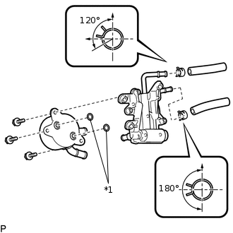
*1
O-ring
Coat 2 new O-rings with ATF and install the O-rings to the grooves of the transmission oil cooler assembly.
Align the transmission oil cooler assembly with the transmission oil thermostat and assemble them with the 3 bolts.
14 N*m
143 kgf*cm
10 ft.*lbf
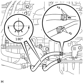
Connect the No. 1 oil cooler inlet hose and No. 1 oil cooler outlet hose to the transmission oil thermostat, and slide the clips to secure it.
Note:Make sure the pinching portion of each clip is facing the direction shown in the illustration.
Connect the No. 1 oil cooler inlet hose and No. 1 oil cooler outlet hose to the oil cooler tube unions, and slide the clips to secure it.
-
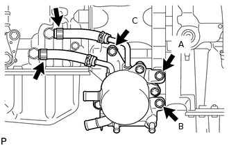
Temporarily install the transmission oil cooler assembly together with the transmission oil thermostat with bolt A. Install bolts B and C and tighten them to the specified torque. Then tighten bolt A to the specified torque.
21 N*m
214 kgf*cm
15 ft.*lbf
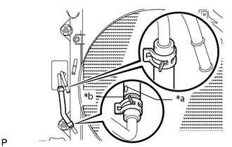
-
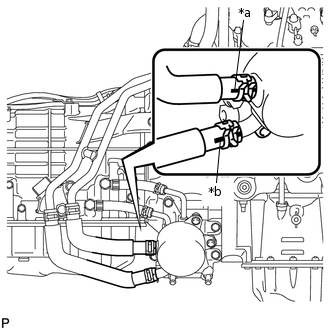
*a
White Paint Mark
*b
Blue Paint Mark
Connect the 2 water by-pass hoses to the transmission oil cooler assembly, and slide the clips to secure it.
Note:Make sure the pinching portion of each clip is facing the direction shown in the illustration.
Make sure the paint mark of each hose is facing outward.
-
INSTALL NO. 2 OIL COOLER INLET HOSE AND NO. 2 OIL COOLER OUTLET HOSE
-
*a
Blue Paint Mark
*b
Pink Paint Mark
Connect the No. 2 oil cooler inlet hose and No. 2 oil cooler outlet hose to the transmission oil thermostat.
Connect the 2 hoses to the No. 1 oil cooler inlet tube and No. 1 oil cooler outlet tube to install them.
Note:Make sure the pinching portion of each clip is facing the direction shown in the illustration.
Make sure the paint mark of each hose is facing outward.
-
INSTALL FRONT EXHAUST PIPE ASSEMBLY
ADD ENGINE COOLANT
ADJUST AUTOMATIC TRANSMISSION FLUID LEVEL
INSPECT FOR COOLANT LEAK
INSTALL FRONT BUMPER COVER (w/ Air Cooled Transmission Oil Cooler)
INSTALL FRONT NO. 1 FENDER APRON TO FRAME SEAL RH
INSTALL FRONT FENDER APRON SEAL RH
INSTALL NO. 1 ENGINE UNDER COVER SUB-ASSEMBLY
INSTALL REAR ENGINE UNDER COVER ASSEMBLY