METER / GAUGE SYSTEM Operating Light Control Rheostat does not Change Light Brightness
DESCRIPTION
The combination meter sub-assembly receives signals from this circuit to adjust the illumination of the meter. The combination meter sub-assembly sets the illumination level based on the user operation of the light control rheostat switch.
Tech Tips
-
The meter illumination level can be adjusted by operating the hazard warning signal switch assembly (light control rheostat switch).
-
The meter illumination dims when the light control switch is turned to the tail, head, or AUTO position at night.
-
Setting the meter illumination to maximum brightness cancels the above dimming of the meter illumination.
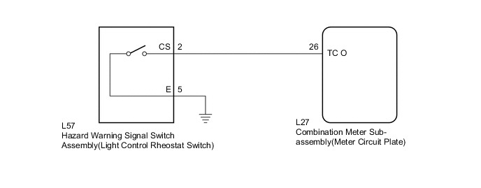
WIRING DIAGRAM
PROCEDURE
-
READ VALUE USING GTS (LIGHT CONTROL SWITCH)
-
Connect the GTS to the DLC3.
-
Turn the power switch on (IG).
-
Turn the GTS on.
-
Enter the following menus: Body Electrical / Combination Meter / Data List.
-
Check the values by referring to the table below.
Combination Meter Tester Display Measurement Item/Range Normal Condition Diagnostic Note Light Control Switch Light control rheostat switch (hazard warning signal switch assembly) / OFF or ON OFF: Light control rheostat switch not pressed - ON: Light control rheostat switch pressed OK The value displayed on the GTS gradually changes as the actual light control rheostat switch operation.
OK 
REPLACE METER CIRCUIT PLATE Click here
NG 
-
-
INSPECT HAZARD WARNING SIGNAL SWITCH ASSEMBLY
-
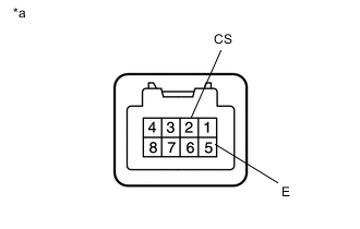
Text in Illustration *a Component without harness connected
(Light Control Rheostat)
Remove the hazard warning signal switch assembly Click here.
-
Measure the resistance according to the value(s) in the table below.
Standard Resistance Tester Connection Switch Condition Specified Condition 2 (CS) - 5 (E) Light control rheostat switch pressed Below 1 Ω Light control rheostat switch not pressed 10 kΩ or higher
NG
REPLACE HAZARD WARNING SIGNAL SWITCH ASSEMBLY Click here
OK
-
-
CHECK HARNESS AND CONNECTOR (COMBINATION METER SUB-ASSEMBLY - HAZARD WARNING SIGNAL SWITCH ASSEMBLY)
-
Disconnect the L27 combination meter sub-assembly connector.
-
Measure the resistance according to the value(s) in the table below.
Standard Resistance Tester Connection Condition Specified Condition L27-26 (TC O) - L57-2 (CS) Always Below 1 Ω L57-5 (E) - Body ground Always Below 1 Ω L27-26 (TC O) - Body ground Always 10 kΩ or higher
OK
REPLACE METER CIRCUIT PLATE Click here
NG
REPAIR OR REPLACE HARNESS OR CONNECTOR
-