SFI SYSTEM, Diagnostic DTC:P2300,P2301,P2303,P2304,P2306 and P2307
| DTC Code | DTC Name |
|---|---|
| P2300 | Ignition Coil "A" Primary Control Circuit Low |
| P2301 | Ignition Coil "A" Primary Control Circuit High |
| P2303 | Ignition Coil "B" Primary Control Circuit Low |
| P2304 | Ignition Coil "B" Primary Control Circuit High |
| P2306 | Ignition Coil "C" Primary Control Circuit Low |
| P2307 | Ignition Coil "C" Primary Control Circuit High |
DESCRIPTION
A direct ignition system is used on this vehicle.
The direct ignition system is a 1-cylinder ignition system in which each cylinder is ignited by one ignition coil and one spark plug is connected to the end of each secondary wiring. A powerful voltage, generated in the secondary wiring, is applied directly to each spark plug. The sparks of the spark plugs pass from the center electrode to the ground electrodes.
DTC No. |
Detection Item |
DTC Detection Condition |
Trouble Area |
MIL |
Memory |
|---|---|---|---|---|---|
P2300 |
Ignition Coil "A" Primary Control Circuit Low |
Open in ignition coil assembly (No. 1 cylinder) circuit. |
|
Comes on |
DTC stored |
P2301 |
Ignition Coil "A" Primary Control Circuit High |
Short to +B in ignition coil assembly (No. 1 cylinder) circuit. |
|
Comes on |
DTC stored |
P2303 |
Ignition Coil "B" Primary Control Circuit Low |
Open in ignition coil assembly (No. 2 cylinder) circuit. |
|
Comes on |
DTC stored |
P2304 |
Ignition Coil "B" Primary Control Circuit High |
Short to +B in ignition coil assembly (No. 2 cylinder) circuit. |
|
Comes on |
DTC stored |
P2306 |
Ignition Coil "C" Primary Control Circuit Low |
Open in ignition coil assembly (No. 3 cylinder) circuit. |
|
Comes on |
DTC stored |
P2307 |
Ignition Coil "C" Primary Control Circuit High |
Short to +B in ignition coil assembly (No. 3 cylinder) circuit. |
|
Comes on |
DTC stored |
MONITOR DESCRIPTION
These DTCs are stored when a malfunction is detected in an ignition coil assembly circuit. If there is an open or short in an ignition coil assembly circuit, the ECM will illuminate the MIL and store a DTC.
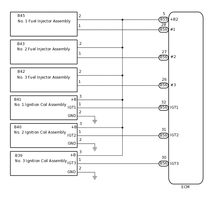
WIRING DIAGRAM
PROCEDURE
PERFORM SPARK TEST
Connect the GTS to the DLC3.
Turn the ignition switch to ON.
Turn the GTS on.
Clear the DTCs.
Powertrain > Engine > Clear DTCs
Turn the ignition switch off and wait for a few minutes.
Shuffle the arrangement of the ignition coil assemblies (among No. 1 to No. 3 cylinders).
Note:Do not change the location of the connectors.
Perform a spark test.
Enter the following menus: Powertrain / Engine / Trouble Codes.
Check for DTCs.
Powertrain > Engine > Trouble Codes
Result
Result
Proceed to
Same DTC output
A
Different ignition coil DTC output
B
CHECK HARNESS AND CONNECTOR (IGNITION COIL ASSEMBLY - ECM)
Disconnect the ignition coil assembly connectors.
Disconnect the fuel injector assembly connectors.
Disconnect the ECM connectors.
Measure the resistance according to the value(s) in the table below.
Standard Resistance
Tester Connection
Condition
Specified Condition
B41-1 (IGT1) - B56-32 (IGT1)
Always
Below 1 Ω
B41-3 (+B) - B55-5 (+B2)
Always
Below 1 Ω
B40-1 (IGT2) - B56-31 (IGT2)
Always
Below 1 Ω
B40-3 (+B) - B55-5 (+B2)
Always
Below 1 Ω
B39-1 (IGT3) - B56-30 (IGT3)
Always
Below 1 Ω
B39-3 (+B) - B55-5 (+B2)
Always
Below 1 Ω
B41-1 (IGT1) or B56-32 (IGT1) - Body ground and other terminals
Always
10 kΩ or higher
B40-1 (IGT2) or B56-31 (IGT2) - Body ground and other terminals
Always
10 kΩ or higher
B39-1 (IGT3) or B56-30 (IGT3) - Body ground and other terminals
Always
10 kΩ or higher
B45-2, B43-2, B42-2, B41-3 (+B), B40-3 (+B), B39-3 (+B) or B55-5 (+B2) - Body ground and other terminals
Always
10 kΩ or higher
Result
Proceed to
OK
NG
NG REPAIR OR REPLACE HARNESS OR CONNECTOR
CHECK HARNESS AND CONNECTOR (IGNITION COIL ASSEMBLY - BODY GROUND)
Disconnect the ignition coil assembly connectors.
Measure the resistance according to the value(s) in the table below.
Standard Resistance
Tester Connection
Condition
Specified Condition
B41-2 (GND) - Body ground
Always
Below 1 Ω
B40-2 (GND) - Body ground
Always
Below 1 Ω
B39-2 (GND) - Body ground
Always
Below 1 Ω
Result
Proceed to
OK
NG
NG REPAIR OR REPLACE HARNESS OR CONNECTOR