HEATER WATER PUMP(for 8GR-FKS) INSTALLATION
CAUTION / NOTICE / HINT
Tech Tips
-
Use the same procedure for RHD and LHD vehicles.
-
The procedure listed below is for LHD vehicles.
PROCEDURE
-
INSTALL NO. 2 WIRING AIR INDICATOR HARNESS SUB-ASSEMBLY
-

Tape Connect the connector.
-
Attach the clamp to install the No. 2 wiring air indicator harness sub-assembly.
-
-
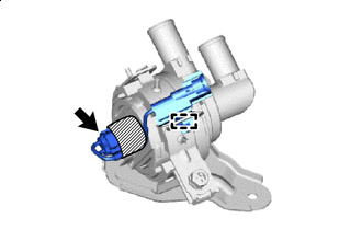
INSTALL HEATER ACCESSORY ASSEMBLY
-
Attach the 4 hose clips to the 2 water hoses.
-

Bolt 
Nut 
Connector Install the heater accessory assembly with the bolt and nut.
- Torque:
- 8.0 N*m { 82 kgf*cm, 71 in.*lbf }
Note
If the removed nut is the same shape as that shown in the illustration, replace it the supplied replacement part.
-
Connect the connector.
-
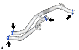
Connect 2 water hoses with its marking aligned as shown in the illustration and install the 2 hose clips.
Note
Do not apply excessive force to the water hose.
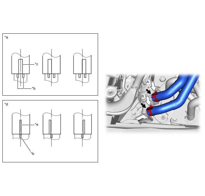
*a View A *b Heater Accessory Assembly Marking *c Water Hose Marking (Green) *d View B *e Water Hose Marking (White) - - -
Connect 2 water hoses with its marking aligned as shown in the illustration and install the 2 hose clips within the range shown in the illustration.
Note
-
Do not apply excessive force to the water hose.
-
Insert the water hose until it bulges but without it sticking out.
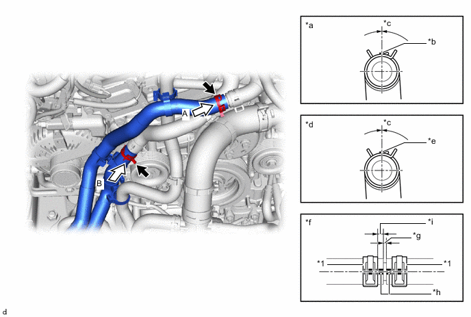
*1 Hose Clip - - *a View A *b Marking (Blue) *c Hose Clip Installation Angle (-15 to 15°) *d View B *e Marking (Yellow) *f Hose Connector Detail *g Bulge *h Marking *i Hose Clip Installation Range (2 to 7 mm (0.0787 to 0.276 in.)) - - -
-
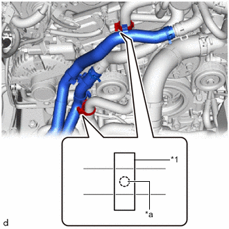
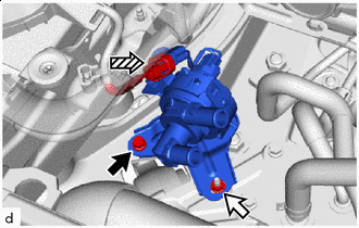
*1 Clamp *a Marking Attach the clamp.
Note
Make sure the marking is hidden in the clamp.
-
w/ In-tank Oil Cooler
-
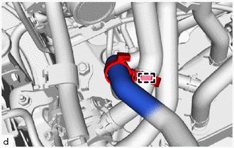
Attach the clamp.
-
-
-
INSTALL AIR CLEANER ASSEMBLY
Note
Check that the air cleaner support is properly installed to the specified position on the air cleaner support bracket and body.
-
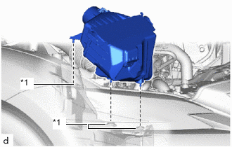
*1 Air Cleaner Support Install the air cleaner assembly to the 3 air cleaner supports.
-
*a Cutout *b Protrusion *c Positioning Stopper *d Stopper Align the protrusion of the air cleaner assembly with the cutout of the air cleaner hose assembly, and connect the air cleaner hose assembly to the air cleaner assembly.
Note
Insert the air cleaner hose assembly until it hits the stopper.
-
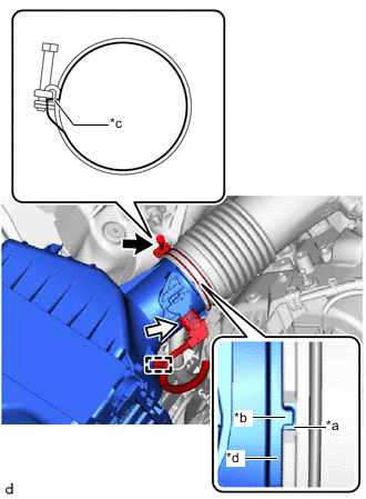
Tighten the hose clamp as shown in the illustration.
Note
Tighten the hose clamp so that it contacts the air cleaner hose assembly positioning stopper.
- Torque:
- 4.0 N*m { 41 kgf*cm, 35 in.*lbf }
-
Connect the connector.
-
Attach the clamp.
-
-
INSTALL NO. 1 AIR CLEANER INLET
-
INSTALL RADIATOR SUPPORT TO CROSSMEMBER BRACE SUB-ASSEMBLY RH
-
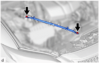
Install the radiator support to crossmember brace sub-assembly RH with the 2 bolts.
- Torque:
- 49 N*m { 500 kgf*cm, 36 ft.*lbf }
-
-
ADD ENGINE COOLANT
-
INSPECT FOR COOLANT LEAK
-
INSTALL LOWER RADIATOR AIR DEFLECTOR
-
INSTALL UPPER RADIATOR SUPPORT SEAL
-
INSTALL RADIATOR COVER PLATE
-
INSTALL V-BANK COVER SUB-ASSEMBLY
-
INSTALL NO. 2 ENGINE UNDER COVER ASSEMBLY
-
INSTALL TRANSMISSION UNDER COVER
-
INSTALL NO. 1 ENGINE UNDER COVER ASSEMBLY