AUTOMATIC HEADLIGHT BEAM LEVEL CONTROL SYSTEM LVL Terminal Circuit
| DTC Code | DTC Name |
|---|---|
| LVL Terminal Circuit |
DESCRIPTION
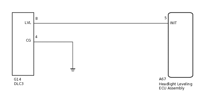
When terminals LVL and CG of the DLC3 are connected, the headlight leveling ECU initializes the height control sensor signal.
WIRING DIAGRAM
CAUTION / NOTICE / HINT
After replacing the headlight leveling ECU, initialization of the ECU is necessary.
PROCEDURE
CHECK HARNESS AND CONNECTOR (DLC3 - HEADLIGHT LEVELING ECU ASSEMBLY)
Disconnect the A67 headlight leveling ECU connector.
Measure the resistance according to the value(s) in the table below.
Standard Resistance
Tester Connection
Condition
Specified Condition
A67-5 (INIT) - G14-8 (LVL)
Always
Below 1 Ω
A67-5 (INIT) - Body ground
Always
10 kΩ or higher
Result
Proceed to
OK
NG
NG REPAIR OR REPLACE HARNESS OR CONNECTOR
CHECK HARNESS AND CONNECTOR (DLC3 - BODY GROUND)
-
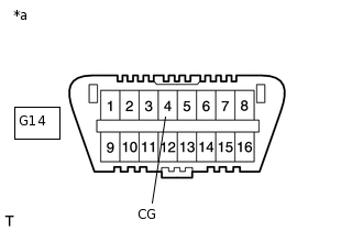
*a
Front view of DLC3
Measure the resistance according to the value(s) in the table below.
Standard Resistance
Tester Connection
Condition
Specified Condition
G14-4 (CG) - Body ground
Always
Below 1 Ω
Result
Proceed to
OK
NG
NG REPAIR OR REPLACE HARNESS OR CONNECTOR
-