AIR CONDITIONING SYSTEM(for Manual Air Conditioning System) Recirculation Damper Servo Motor Circuit
| DTC Code | DTC Name |
|---|---|
| Recirculation Damper Servo Motor Circuit |
DESCRIPTION
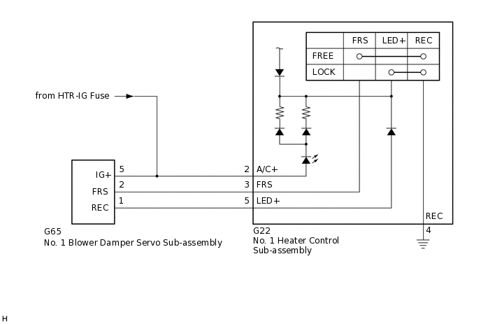
The No. 1 blower damper servo sub-assembly and No. 1 heater control sub-assembly are powered through the HTR-IG fuse. Operating the No. 1 heater control sub-assembly drives the the No. 1 blower damper servo sub-assembly to switch between fresh and recirculation mode.
WIRING DIAGRAM
CAUTION / NOTICE / HINT
Inspect the fuses for circuits related to this system before performing the following procedure.
PROCEDURE
INSPECT NO. 1 BLOWER DAMPER SERVO SUB-ASSEMBLY
Remove the No. 1 blower damper servo sub-assembly.
Connect a positive (+) lead from the battery to terminal 5 (IG+) and negative (-) lead to terminal 2 (FRS), then check that the arm turns to the fresh side smoothly.
Connect a positive (+) lead from the battery to terminal 5 (IG+) and negative (-) lead to terminal 1 (REC), then check that the arm turns to the recirculation side smoothly.
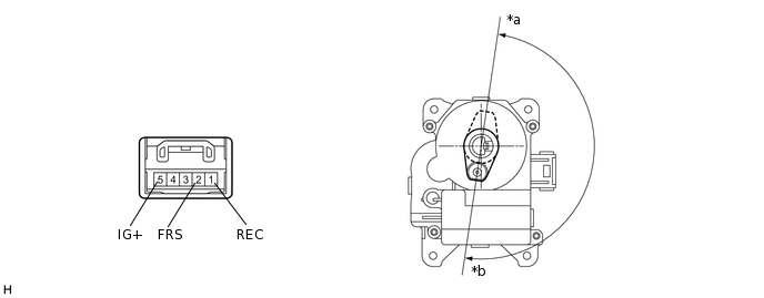
*a
Recirculation Position
*b
Fresh Position
Result
Proceed to
OK
NG
INSPECT NO. 1 HEATER CONTROL SUB-ASSEMBLY
-
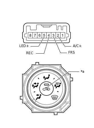
*a
Recirculation/Fresh Switch
Measure the resistance.
Remove the No. 1 heater control sub-assembly.
Measure the resistance according to the value(s) in the table below.
Standard Resistance
Tester Connection
Switch Condition
Specified Condition
3 (FRS) - 4 (REC)
Recirculation/fresh switch off
Below 1 Ω
3 (FRS) - 4 (REC)
Recirculation/fresh switch on
10 kΩ or higher
5 (LED+) - 4 (REC)
Recirculation/fresh switch off
10 kΩ or higher
5 (LED+) - 4 (REC)
Recirculation/fresh switch on
Below 1 Ω
Check that the indicator light comes on.
Turn the recirculation/fresh switch to the on position.
Connect a positive (+) lead from the battery to terminal 2 (A/C+) and negative (-) lead to terminal 4 (REC), and check that the indicator light comes on.
OK
The indicator light comes on.
Result
Proceed to
OK
NG
-
CHECK HARNESS AND CONNECTOR (NO. 1 BLOWER DAMPER SERVO SUB-ASSEMBLY - BATTERY)
-
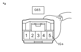
*a
Front view of harness connector
(to No. 1 Blower Damper Servo Sub-assembly)
Disconnect the No. 1 blower damper servo sub-assembly connector.
Measure the voltage according to the value(s) in the table below.
Standard Voltage
Tester Connection
Switch Condition
Specified Condition
G65-5 (IG+) - Body ground
Ignition switch off
Below 1 V
G65-5 (IG+) - Body ground
Ignition switch ON
11 to 14 V
Result
Proceed to
OK
NG
NG REPAIR OR REPLACE HARNESS OR CONNECTOR
-
CHECK HARNESS AND CONNECTOR (NO. 1 HEATER CONTROL SUB-ASSEMBLY - BATTERY)
-
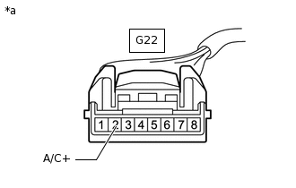
*a
Front view of wire harness connector
(to No. 1 Heater Control Sub-assembly)
Disconnect the No. 1 heater control sub-assembly connector.
Measure the voltage according to the value(s) in the table below.
Standard Voltage
Tester Connection
Switch Condition
Specified Condition
G22-2 (A/C+) - Body ground
Ignition switch off
Below 1 V
G22-2 (A/C+) - Body ground
Ignition switch ON
11 to 14 V
Result
Proceed to
OK
NG
NG REPAIR OR REPLACE HARNESS OR CONNECTOR
-
CHECK HARNESS AND CONNECTOR (NO. 1 HEATER CONTROL SUB-ASSEMBLY - BODY GROUND)
-
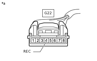
*a
Front view of wire harness connector
(to No. 1 Heater Control Sub-assembly)
Disconnect the No. 1 heater control sub-assembly connector.
Measure the resistance according to the value(s) in the table below.
Standard Resistance
Tester Connection
Condition
Specified Condition
G22-4 (REC) - Body ground
Always
Below 1 Ω
Result
Proceed to
OK
NG
NG REPAIR OR REPLACE HARNESS OR CONNECTOR
-
CHECK HARNESS AND CONNECTOR (NO. 1 HEATER CONTROL SUB-ASSEMBLY - NO. 1 BLOWER DAMPER SERVO SUB-ASSEMBLY)
Disconnect the G22 No. 1 heater control sub-assembly connector.
Disconnect the G65 No. 1 blower damper servo sub-assembly connector.
Measure the resistance according to the value(s) in the table below.
Standard Resistance
Tester Connection
Condition
Specified Condition
G22-3 (FRS) - G65-2 (FRS)
Always
Below 1 Ω
G22-5 (LED+) - G65-1 (REC)
Always
Below 1 Ω
G22-3 (FRS) - Body ground
Always
10 kΩ or higher
G22-5 (LED+) - Body ground
Always
10 kΩ or higher
Result
Proceed to
OK
NG
NG REPAIR OR REPLACE HARNESS OR CONNECTOR