ECD SYSTEM, Diagnostic DTC:P0030
| DTC Code | DTC Name |
|---|---|
| P0030 | HO2S Heater Control Circuit Bank 1 Sensor 1 |
DESCRIPTION
The air fuel ratio sensor is a broadband air fuel ratio sensor. The broadband air fuel ratio sensor measures the remaining oxygen in the exhaust gas. Fluctuations in the value of the remaining oxygen are sent to the ECM as a voltage signal.
The air fuel ratio sensor is used as both a control sensor and monitoring sensor in diesel engines. The lambda air fuel ratio sensor is necessary to ensure the value of the exhaust gas is within compliance. The air fuel ratio sensor is necessary for calculating the average amount value for the injectors. The lambda air fuel ratio sensor measures the air fuel ratio. If there is a deviation, the ECM changes the exhaust gas recirculation rate to optimize the air fuel ratio. Adjusting the average amount value is not a control operation which is performed. air fuel ratio sensor deviation is "learned" to the characteristic map and stored temporarily by the ECM.
The sensor system of the broadband air fuel ratio sensor is composed of several thin layers of zirconium dioxide ceramic. The heating element within the laminate ensures the required operating temperature of at least 760°C. The broadband air fuel ratio sensor includes two cells, a measurement cell and a reference cell. These two cells are coated in electrodes made of platinum.
Although the DTC titles say HO2S heater, these DTCs relate to the air fuel ratio sensor heater.
Sensor 1 is the sensor installed in the exhaust manifold converter in the front of the catalytic converter.
Sensor 2 is the sensor installed in the exhaust manifold converter in the rear of the catalytic converter.
DTC No. |
Detection Item |
DTC Detection Condition |
Trouble Area |
MIL |
Memory |
|---|---|---|---|---|---|
P0030 |
HO2S Heater Control Circuit Bank 1 Sensor 1 |
Ground short in air fuel ratio sensor (for sensor 1) heater circuit for 2 seconds. (3 trip detection logic) |
|
Does not come on |
DTC stored |
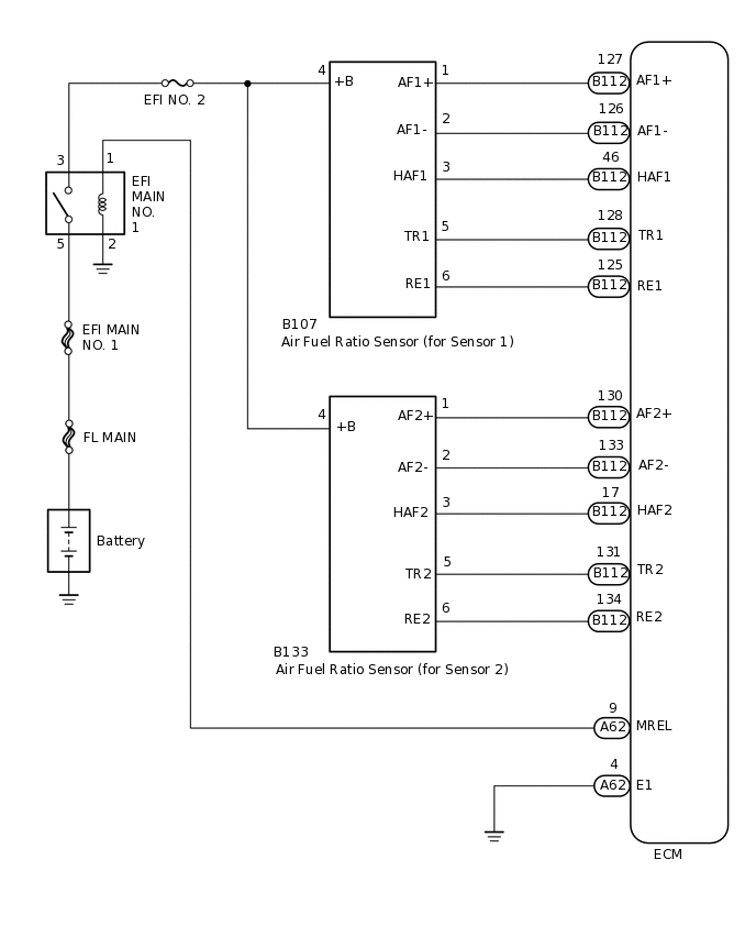
WIRING DIAGRAM
CAUTION / NOTICE / HINT
When replacing the ECM and/or air fuel ratio sensor, the ECM needs registration and initialization.
Inspect the fuses for circuits related to this system before performing the following inspection procedure.
When the ECM must be replaced, before replacing the ECM, perform the "Learning Values Save" function using the GTS. Then after installing the new ECM, perform all of the initialization/registrations for the "Learning Values Write" function by following the instructions shown on the GTS display.
Read freeze frame data using the GTS. Freeze frame data records the engine condition when malfunctions are detected. When troubleshooting, freeze frame data can help determine if the vehicle was moving or stationary, if the engine was warmed up or not, and other data from the time the malfunction occurred.
PROCEDURE
INSPECT AIR FUEL RATIO SENSOR ((FOR SENSOR 1) (HEATER RESISTANCE))
Inspect the air fuel ratio sensor (for sensor 1).
Result
Proceed to
OK
NG
NG REPLACE AIR FUEL RATIO SENSOR (FOR SENSOR 1)Click here
CHECK HARNESS AND CONNECTOR (AIR FUEL RATIO SENSOR (FOR SENSOR 1) - ECM)
Disconnect the air fuel ratio sensor (for sensor 1) connector.
Disconnect the ECM connector.
Measure the resistance according to the value(s) in the table below.
Standard Resistance
Tester Connection
Condition
Specified Condition
B107-1 (AF1+) - B112-127 (AF1+)
Always
Below 1 Ω
B107-2 (AF1-) - B112-126 (AF1-)
Always
Below 1 Ω
B107-3 (HAF1) - B112-46 (HAF1)
Always
Below 1 Ω
B107-5 (TR1) - B112-128 (TR1)
Always
Below 1 Ω
B107-6 (RE1) - B112-125 (RE1)
Always
Below 1 Ω
B107-1 (AF1+) or B112-127 (AF1+) - Body ground
Always
10 kΩ or higher
B107-2 (AF1-) or B112-126 (AF1-) - Body ground
Always
10 kΩ or higher
B107-3 (HAF1) or B112-46 (HAF1) - Body ground
Always
10 kΩ or higher
B107-5 (TR1) or B112-128 (TR1) - Body ground
Always
10 kΩ or higher
B107-6 (RE1) or B112-125 (RE1) - Body ground
Always
10 kΩ or higher
Result
Proceed to
OK
NG
NG REPAIR OR REPLACE HARNESS OR CONNECTORClick here
CHECK HARNESS AND CONNECTOR (POWER SOURCE)
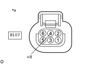
*a
Front view of wire harness connector
(to Air Fuel Ratio Sensor (for Sensor 1))
Disconnect the air fuel ratio sensor (for sensor 1) connector.
Turn the ignition switch to ON.
Measure the voltage according to the value(s) in the table below.
Standard Voltage
Tester Connection
Switch Condition
Specified Condition
B107-4 (+B) - Body ground
Ignition switch ON
11 to 14 V
Result
Proceed to
OK
NG
NG CHECK HARNESS AND CONNECTOR (AIR FUEL RATIO SENSOR (FOR SENSOR 1) - EFI MAIN NO. 1 RELAY)Click here
REPLACE ECM
Replace the ECM.
Result
Proceed to
NEXT
NEXT CONFIRM WHETHER MALFUNCTION HAS BEEN SUCCESSFULLY REPAIREDClick here
CHECK HARNESS AND CONNECTOR (AIR FUEL RATIO SENSOR (FOR SENSOR 1) - EFI MAIN NO. 1 RELAY)
Disconnect the air fuel ratio sensor (for sensor 1) connector.
Remove the EFI MAIN NO. 1 relay from the engine room and junction block.
Measure the resistance according to the value(s) in the table below.
Standard Resistance
Tester Connection
Condition
Specified Condition
B107-4 (+B) - 3 (EFI MAIN NO. 1 relay holder)
Always
Below 1 Ω
B107-4 (+B) or 3 (EFI MAIN NO. 1 relay holder) - Body ground
Always
10 kΩ or higher
Result
Proceed to
OK
NG
NG REPAIR OR REPLACE HARNESS OR CONNECTORClick here
CHECK ECM POWER SOURCE CIRCUIT
Check the ECM power source circuit.
Result
Proceed to
NEXT
NEXT CONFIRM WHETHER MALFUNCTION HAS BEEN SUCCESSFULLY REPAIREDClick here
REPAIR OR REPLACE HARNESS OR CONNECTOR
Repair or replace the harness or connector.
Result
Proceed to
NEXT
CONFIRM WHETHER MALFUNCTION HAS BEEN SUCCESSFULLY REPAIRED
Connect the GTS to the DLC3.
Turn the ignition switch to ON and turn the GTS on.
Clear the DTCs.
Powertrain > Engine and ECT > Clear DTCs
Turn the ignition switch off and wait for 60 seconds or more [A].
Perform road test [B].
Repeat [A] and [B] for the number of trips detected.
Enter the following menus: Powertrain / Engine and ECT / Trouble Codes.
Powertrain > Engine and ECT > Trouble Codes
Confirm that the DTC is not output again.
Result
Proceed to
NEXT
NEXT END
REPLACE AIR FUEL RATIO SENSOR (FOR SENSOR 1)
Replace the air fuel ratio sensor (for sensor 1).
Perform the O2 sensor learning value reset.
Result
Proceed to
NEXT
NEXT CONFIRM WHETHER MALFUNCTION HAS BEEN SUCCESSFULLY REPAIREDClick here