SIMPLE INTELLIGENT PARKING ASSIST SYSTEM, Diagnostic DTC:C1625
| DTC Code | DTC Name |
|---|---|
| C1625 | Open or Short in Steering Angle Sensor +B |
DESCRIPTION
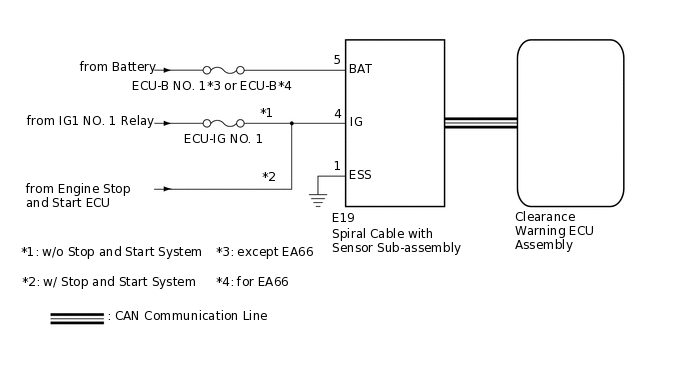
This DTC is stored when the clearance warning ECU assembly receives a steering angle sensor power supply malfunction signal via CAN communication from the spiral cable with sensor sub-assembly.
DTC No. |
Detection Item |
DTC Detection Condition |
Trouble Area |
|---|---|---|---|
C1625 |
Open or Short in Steering Angle Sensor +B |
Open or short in steering angle sensor power source |
|
*: w/ Stop and Start System
WIRING DIAGRAM
CAUTION / NOTICE / HINT
Inspect the fuses for circuits related to this system before performing the following procedure.
Depending on the parts that are replaced during vehicle inspection or maintenance, performing initialization may be needed. Refer to Initialization.
PROCEDURE
CHECK HARNESS AND CONNECTOR (SPIRAL CABLE WITH SENSOR SUB-ASSEMBLY - BODY GROUND)
Disconnect the E19 spiral cable with sensor sub-assembly connector.
Measure the resistance according to the value(s) in the table below.
Standard Resistance
Tester Connection
Condition
Specified Condition
E19-1 (ESS) - Body ground
Always
Below 1 Ω
Result
Proceed to
OK
NG
NG REPAIR OR REPLACE HARNESS OR CONNECTOR
CHECK HARNESS AND CONNECTOR (SPIRAL CABLE WITH SENSOR SUB-ASSEMBLY BATTERY POWER SUPPLY)
Disconnect the E19 spiral cable with sensor sub-assembly connector.
Measure the voltage according to the value(s) in the table below.
Standard Voltage
Tester Connection
Condition
Specified Condition
E19-5 (BAT) - E19-1 (ESS)
Always
11 to 14 V
Result
Proceed to
OK
NG
NG REPAIR OR REPLACE HARNESS OR CONNECTOR
CHECK HARNESS AND CONNECTOR (SPIRAL CABLE WITH SENSOR SUB-ASSEMBLY IG POWER SUPPLY)
Disconnect the E19 spiral cable with sensor sub-assembly connector.
Measure the voltage according to the value(s) in the table below.
Standard Voltage
Tester Connection
Condition
Specified Condition
E19-4 (IG) - E19-1 (ESS)
Ignition switch ON
11 to 14 V*1
9.5 to 14 V*2
*1: w/o Stop and Start System
*2: w/ Stop and Start System
Result
Result
Proceed to
OK
A
NG (w/o Stop and Start System)
B
NG (w/ Stop and Start System)
C
B REPAIR OR REPLACE HARNESS OR CONNECTOR