POWER STEERING SYSTEM, Diagnostic DTC:C1511,C1512,C1513 and C1514
| DTC Code | DTC Name |
|---|---|
| C1511 | Torque Sensor Circuit Malfunction |
| C1512 | Torque Sensor Circuit Malfunction |
| C1513 | Torque Sensor Circuit Malfunction |
| C1514 | Torque Sensor Power Supply Abnormal |
DESCRIPTION
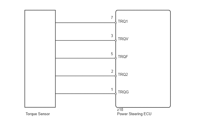
The torque sensor converts the rotation torque input to the steering wheel into an electrical signal and sends it to the power steering ECU. Based on this signal, the ECU detects steering effort.
DTC Code |
DTC Detection Condition |
Trouble Area |
|---|---|---|
C1511 |
A torque sensor (TRQ1) signal error or stop. |
|
C1512 |
A torque sensor (TRQ2) signal error or stop. |
|
C1513 |
The deviation between torque sensor TRQ1 and TRQ2 exceeds a specified value. |
|
C1514 |
A torque sensor power supply voltage error. |
WIRING DIAGRAM
CAUTION / NOTICE / HINT
If the power steering ECU assembly is replaced, perform the assist map writing (Click here).
PROCEDURE
CHECK CONNECTOR CONNECTION CONDITION (TORQUE SENSOR - POWER STEERING ECU)
-
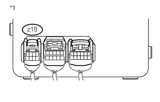
Check the connection condition of the z18 torque sensor connector.
OK
Torque sensor connector is securely connected to the power steering ECU.
Table 1. Text in Illustration *1
Component with harness connected
(Power Steering ECU)
CONNECT CONNECTOR SECURELY
-
CHECK POWER STEERING ECU ASSEMBLY
Turn the ignition switch off.
Turn the ignition switch to ON.
-
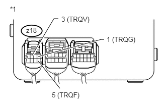
Measure the voltage according to the value(s) in the table below.
Standard Voltage
Tester Connection
Switch Condition
Specified Condition
z18-3 (TRQV) - z18-1 (TRQG)
Ignition switch ON
8.5 to 11 V
z18-5 (TRQF) - z18-1 (TRQG)
Ignition switch ON
3.28 to 3.32 V
Table 2. Text in Illustration *1
Component with harness connected
(Power Steering ECU)
CHECK STEERING COLUMN ASSEMBLY
Turn the ignition switch off.
Turn the ignition switch to ON.
-
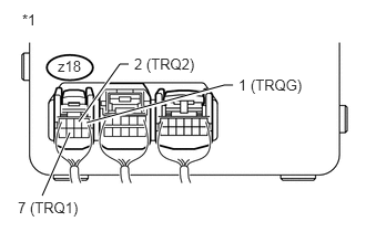
Measure the voltage according to the value(s) in the table below.
Standard Voltage
Tester Connection
Condition
Specified Condition
z18-7 (TRQ1) - z18-1 (TRQG)
Engine running, steering wheel not turned (without load)
2.3 to 2.7 V
Engine running, steering wheel turned to right with vehicle stopped
2.5 to 4.04 V
Engine running, steering wheel turned to left with vehicle stopped
0.95 to 2.5 V
z18-2 (TRQ2) - z18-1 (TRQG)
Engine running, steering wheel not turned (without load)
2.3 to 2.7 V
Engine running, steering wheel turned to right with vehicle stopped
0.95 to 2.5 V
Engine running, steering wheel turned to left with vehicle stopped
2.5 to 4.04 V
Add the voltage measured at terminal TRQ1 minus 2.5 V to the voltage measured at terminal TRQ2 minus 2.5 V.
OK
Below 0.25 V (Absolute value)
Table 3. Text in Illustration *1
Component with harness connected
(Power Steering ECU)