SFI SYSTEM(w/o Canister Pump Module), Diagnostic DTC:P003312, P00C012
| DTC Code | DTC Name |
|---|---|
| P003312 | Turbocharger / Supercharger Bypass Valve "A" Control Circuit Short to Battery |
| P00C012 | Turbocharger/Supercharger Bypass Valve "B" Control Circuit Short to Battery |
DESCRIPTION
The air by-pass valve assembly is installed in the air outlet duct. It opens and closes in response to drive commands from the ECM. During normal boosting, the air by-pass valve assembly is closed, and when the throttle valve is closed while the boost pressure is applied, the air by-pass valve assembly opens and the excess pressure between the turbocharger and throttle valve is released to prevent the surge phenomenon*.
*: This phenomenon is when the intake air flow reverses. As a result, an abnormal noise is easily generated during deceleration.
| DTC No. | Detection Item | DTC Detection Condition | Trouble Area | MIL | Memory | Note |
|---|---|---|---|---|---|---|
| P003312 | Turbocharger / Supercharger Bypass Valve "A" Control Circuit Short to Battery | Short circuit in air by-pass valve assembly (bank 1) circuit and power supply circuit (1 trip detection logic). |
|
- | DTC stored | SAE: P0035 |
| P00C012 | Turbocharger/Supercharger Bypass Valve "B" Control Circuit Short to Battery | Short circuit in air by-pass valve assembly (bank 2) circuit and power supply circuit (1 trip detection logic). |
|
- | DTC stored | SAE: P00C2 |
MONITOR DESCRIPTION
The ECM monitors the output voltage while the air by-pass valve assembly is operating.
The air by-pass valve assembly turns on and off according to ON/OFF switching of a transistor inside the ECM.
If a continuous mismatch occurs between the ECM transistor state and the output voltage, the ECM determines there is a malfunction in the air by-pass valve assembly circuit and stores a DTC.
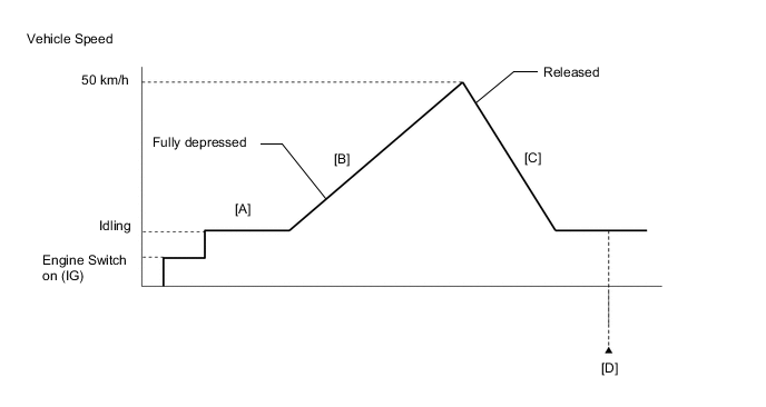
CONFIRMATION DRIVING PATTERN
-
Connect the GTS to the DLC3.
-
Turn the engine switch on (IG) and turn the GTS on.
-
Clear the DTCs (even if no DTCs are stored, perform the clear DTC procedure).
-
Turn the engine switch off and wait for at least 30 seconds.
-
Turn the engine switch on (IG) and turn the GTS on.
-
Start the engine and warm it up until the engine coolant temperature reaches 75°C (167°F) or higher [A].
-
Accelerate to 50 km/h (31 mph) or more with the accelerator pedal fully depressed [B].
CAUTION:
When performing the confirmation driving pattern, obey all speed limits and traffic laws.
-
Quickly release the accelerator pedal from the fully depressed position [C].
-
Enter the following menus: Powertrain / Engine / Trouble Codes [D].
-
Read the pending DTCs.
Tech Tips
-
If a pending DTC is output, the system is malfunctioning.
-
If a pending DTC is not output, perform the following procedure.
-
-
Enter the following menus: Powertrain / Engine / Utility / All Readiness.
-
Input the DTC: P003312 or P00C012.
-
Check the DTC judgment result.
GTS Display Description NORMAL
-
DTC judgment completed
-
System normal
ABNORMAL
-
DTC judgment completed
-
System abnormal
INCOMPLETE
-
DTC judgment not completed
-
Perform driving pattern after confirming DTC enabling conditions
Tech Tips
-
If the judgment result shows NORMAL, the system is normal.
-
If the judgment result shows ABNORMAL, the system has a malfunction.
-
If the judgment result shows INCOMPLETE, perform steps [B] through [D] again.
-
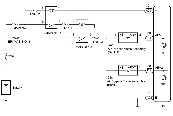
WIRING DIAGRAM
CAUTION / NOTICE / HINT
Note
Inspect the fuses for circuits related to this system before performing the following procedure.
Tech Tips
-
Read Freeze Frame Data using the GTS. The ECM records vehicle and driving condition information as Freeze Frame Data the moment a DTC is stored. When troubleshooting, Freeze Frame Data can help determine if the vehicle was moving or stationary, if the engine was warmed up or not, if the air fuel ratio was lean or rich, and other data from the time the malfunction occurred.
-
Bank 1 refers to the bank that includes the No. 1 cylinder*.
*: The No. 1 cylinder is the cylinder which is farthest from the transmission.
-
Bank 2 refers to the bank that does not include the No. 1 cylinder.
DTC Suspected Area P003312 Bank 1 P00C012 Bank 2
PROCEDURE
-
INSPECT AIR BY-PASS VALVE ASSEMBLY
-
Inspect the air by-pass valve assembly.
Result Proceed to OK NG
NG 
REPLACE AIR BY-PASS VALVE ASSEMBLY Click here
OK 
-
-
CHECK HARNESS AND CONNECTOR (AIR BY-PASS VALVE ASSEMBLY - ECM)
-
Disconnect the air by-pass valve assembly connector.
-
Disconnect the ECM connector.
-
Measure the resistance according to the value(s) in the table below.
Standard Resistance Tester Connection Condition Specified Condition D36-2 (ABV) or D1-30 (ABV) - Other terminals Always 10 kΩ or higher D38-2 (ABV2) or D1-29 (ABV2) - Other terminals Always 10 kΩ or higher Result Proceed to OK NG
NG
REPAIR OR REPLACE HARNESS OR CONNECTOR
OK
-
-
CLEAR DTC
-
Connect the GTS to the DLC3.
-
Turn the engine switch on (IG).
-
Turn the GTS on.
-
Clear the DTCs.
Powertrain > Engine > Clear DTCs -
Turn the engine switch off and wait for at least 30 seconds.
Result Proceed to NEXT
NEXT
-
-
CHECK WHETHER DTC OUTPUT RECURS (DTC P003312 OR P00C012)
-
Drive the vehicle in accordance with the driving pattern described in Confirmation Driving Pattern.
-
Enter the following menus: Powertrain / Engine / Utility / All Readiness.
Powertrain > Engine > UtilityTester Display All Readiness -
Input the DTC: P003312 or P00C012.
-
Check the DTC judgment result.
Result Result Proceed to NORMAL
(DTCs are not output)
A ABNORMAL
(DTC P003312 or P00C012 is output)
B
A
CHECK FOR INTERMITTENT PROBLEMS Click here
B
REPLACE ECM Click here
-