FUEL SYSTEM
-
FUNCTION OF MAIN COMPONENTS
-
The D-4S system has following components and functions:
Component Function Fuel Suction Tube with Pump and Gage Assembly (for Low Pressure) Sends fuel (400 kPa) from the fuel tank assembly to the fuel pump assembly (for high pressure) and fuel injector assembly (for port injection). Fuel Pump Assembly (for High Pressure) Increases the pressure of the fuel from the fuel suction tube with pump and gage assembly (for low pressure) to a pressure of 2.4 to 20 MPa and sends it to the fuel delivery pipe sub-assembly (for direct injection). Spill Control Valve Closes and opens the fuel flow path to the high-pressure fuel system in accordance with signals from the Electronic Driver Unit (Injector Driver). Fuel Pipe Sub-assembly (for Port Injection) Delivers the low-pressure fuel to the fuel injector assembly (for port injection). Fuel Delivery Pipe Sub-assembly (for Direct Injection) Delivers the high-pressure fuel to the fuel injector assembly (for direct injection). Fuel Pressure Pulsation Damper Assembly Reduces the fuel pressure fluctuation (pulsation) and noise. Fuel Pressure Sensor Senses the fuel pressure and outputs a signal to the ECM. Fuel Relief Valve Assembly If the fuel pressure in the fuel delivery pipe (for Direct Injection) is abnormally high, the fuel relief valve assembly discharges some of the fuel to the fuel pump assembly (for high pressure) in order to limit the pressure. Fuel Injector Assembly (for Port Injection) Injects a calculated (by the ECM) quantity of 400 kPa (low pressure) fuel into the intake port. Fuel Injector Assembly (for Direct Injection) Injects a calculated (by the Injector Driver) quantity of 2.4 to 20 MPa (high pressure) fuel directly into the combustion chamber. Electronic Driver Unit (Injector Driver) Transforms signals sent from the ECM (fuel injection request and high-pressure fuel injection volume control) into high-pressure and high-voltage operation signals in order to operate the fuel injector assemblies (for direct injection) and spill control valve at high-speed. ECM Depending on the vehicle condition, and based on signals from various sensors, the ECM calculates the optimal injection timing and volume, and controls the fuel injector assembly (for direct injection) and fuel pump assembly (for high pressure).
-
-
CONSTRUCTION
-
Fuel Suction Tube with Pump and Gage Assembly (for Low Pressure)
-
A compact fuel suction tube with pump and gage assembly is used. Its basic components are a fuel pump, a fuel filter, a pressure regulator and a fuel sender gauge assembly.
-
The fuel suction tube with pump and gage assembly (for low pressure) is located in the fuel tank assembly. This fuel pump pressurizes the fuel from the fuel tank assembly and sends the fuel to the high-pressure and low-pressure fuel systems.
-
A system to turn off the circuit opening relay and prevent fuel leakage during an impact (when the airbag is deployed) by means of a signal from the airbag sensor assembly has been adopted to ensure safety.
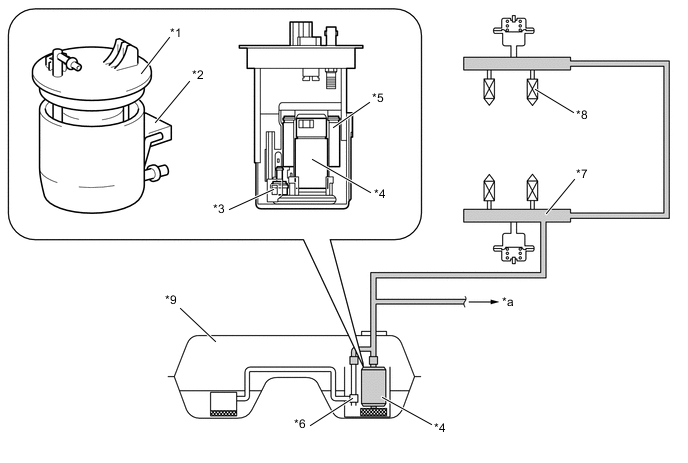
Text in Illustration *1 Fuel Suction Tube with Pump and Gage Assembly *2 No. 2 Fuel Sender Gage Assembly *3 Fuel Pressure Regulator *4 Fuel Pump (for Low Pressure) *5 Fuel Filter *6 Jet Pump *7 Fuel Pipe Sub-assembly (for Port Injection) *8 Fuel Injector Assembly (for Port Injection) *9 Fuel Tank Assembly - - *a to High-pressure Fuel System - - 
Low-pressure Fuel - -
-
-
Fuel Pump Assembly (for High Pressure)
-
The high-pressure fuel pump is constructed with a check valve that mechanically opens and closes the passage to the fuel delivery pipe and plunger that operate and pressurize the fuel by means of a intake camshaft LH and electromagnetic spill valve that regulate high-pressure fuel, and with a relief valve for when abnormal fuel pressure occurs. The electromagnetic spill valve, check valve and relief valve are integrated together, making the system lighter and more compact. A pulsation damper has been fitted to the low-pressure fuel intake from the fuel tank to reduce fuel pulsation.
-
The high-pressure fuel pump is attached to the camshaft housing sub-assembly LH and is driven by the cam attached to the front end of the intake camshaft.
-
Fuel is pressurized by the up-and-down motion of the pump plunger. An electromagnetic spill valve attached to the pump intake side closes with optimal timing during the pressurization process in order to maintain the required fuel pressure and fuel volume. If it closes too quickly, the plunger's effective stroke grows longer, resulting in higher fuel pressure.
-
Fuel pressurized by the plunger applies pressure on the check valve (60 kPa) to open it, transferring pressure to the fuel delivery pipe sub-assembly, and is regulated to between 2.4 and 20 MPa (approximately 24 to 200 atmospheres).
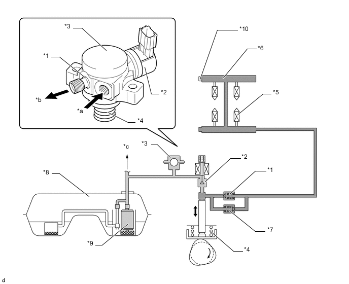
Text in Illustration *1 Check Valve *2 Spill Control Valve *3 Pulsation Damper *4 Plunger *5 Fuel Injector Assembly (for Direct Injection) *6 Fuel Delivery Pipe Sub-assembly (for Direct Injection) *7 Fuel Relief Valve *8 Fuel Tank Assembly *9 Fuel Pump (for Low Pressure) *10 Fuel Pressure Sensor *a From Fuel Suction Tube with Pump and Gage Assembly (for Low Pressure) *b To Fuel Delivery Pipe Sub-assembly (for Direct Injection) *c To Low-pressure Fuel System - - Low-pressure Fuel 
High-pressure Fuel
-
-
Fuel Delivery Pipe Sub-assembly (for Port Injection)
-
Stamped steel fuel delivery pipes are used for the fuel pipe sub-assembly (for port injection).
-
A fuel pressure pulsation damper assembly is mounted on the left and right delivery pipes respectively to reduce fuel pulsation.
-
A quick connector has been adopted for the connecting pipe between the left-hand and right-hand fuel delivery pipes to improve serviceability.
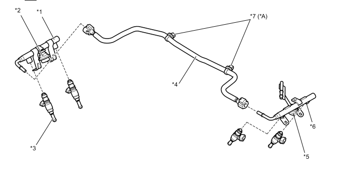
Text in Illustration *A Models with M/T for the Australia and New Zealand Packages - - *1 No. 1 Fuel Pipe Sub-assembly (for Port Injection) *2 Fuel Pressure Pulsation Damper RH *3 Fuel Injector Assembly (for Port Injector) *4 No. 2 Fuel Delivery Pipe Sub-assembly *5 Fuel Pressure Pulsation Damper LH *6 No. 2 Fuel Pipe Sub-assembly (for Port Injection) *7 Clamp - -
-
-
Fuel Delivery Pipe Sub-assembly (for Direct Injection)
-
Carbon steel fuel delivery pipes are used for the fuel delivery pipe (for direct injection).
-
A fuel pressure sensor is installed on the fuel delivery pipe RH for direct injection.
-
A tapering seal metal fitting has been adopted for the connecting pipe between the left-hand/right-hand fuel delivery pipes, as well as from the high-pressure fuel pump to the left-hand fuel delivery pipe.
-
An injector clamp is provided for each area of the fuel delivery pipe where a fuel injector assembly (for direct injection) is installed. This clamp applies a constant spring force to the injector to prevent the injector from moving when the combustion pressure is applied to the injector while the engine is being started, during which the fuel pressure is low. As a result, the clamp increases the sealing performance of the injector, while reducing vibration and noise.
-
O-rings and backup rings are used in the areas in which the fuel injector assembly (for direct injection) and fuel delivery pipe (for direct injection) are joined. This reduces the transmission of the operating sounds of the fuel injector assembly (for direct injection), enhances quiet operation, and ensures the sealing performance of the joined areas.
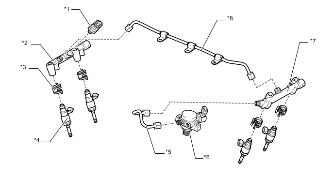
Text in Illustration *1 Fuel Pressure Sensor *2 Fuel Delivery Pipe RH (for Direct Injection) *3 No. 1 Injector Holder *4 Fuel Injector Assembly (for Direct Injection) *5 No. 2 Fuel Delivery Pipe *6 Fuel Pump Assembly (for High pressure) *7 Fuel Delivery Pipe LH (for Direct Injection) *8 Fuel Pipe
-
-
Fuel Injector Assembly (for Port Injection)
-
Compact and lightweight 12-hole injectors are used as fuel injectors for port injection.
-
Fuel consumption has been reduced and emission performance has been improved by facilitating the atomization of fuel and reducing fuel deposition on the intake port.
-
The nozzle has been extended to optimize the shape of the injection spray with the aim of improving fuel-air mixture formation.
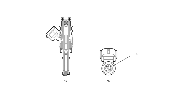
Text in Illustration *1 Injection Nozzle - - *a Cross Section *b Bottom Side View
-
-
Fuel Injector Assembly (for Direct Injection)
-
High-pressure slit-nozzle injectors that have slit-shaped orifices for use as fuel injectors for direct injection have been adopted.
-
The fuel is atomized by these injectors, and it is injected into the combustion chamber while simultaneously spreading out like a fan and mixing with a large amount of air. By doing so, spatial dispersion of the injection spray is improved, achieving a homogeneous mixture while improving power and performance.
-
Because the injector is exposed to the inside of the combustion chamber, the end is treated with a special coating to prevent combustion gases from leaving deposits on it.
-
An insulator has been adopted for the area in which the injector comes in contact with the cylinder head, and a Teflon shaft seal has been adopted in the cylinder pressure seal, reducing vibration and noise while improving sealability.
-
The injectors are controlled through high-voltage and a constant-current control based on instructions from the ECM. This allows the injectors to inject high-pressure fuel in a short amount of time.
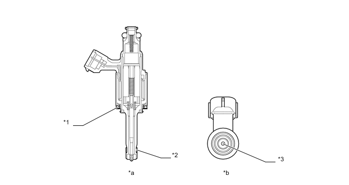
Text in Illustration *1 Insulator *2 Teflon Shaft Seal *3 Injection Nozzle - - *a Cross Section *b Bottom Side View
-
-
Fuel Tank Assembly
-
A multi-layer plastic fuel tank is used. The multiplex layered plastic fuel tank consists of six layers of four types of materials, and one of those is a recyclable material to address environmental concerns.
-
A fuel drain mark has been provided at the lowest position of the fuel tank assembly. When dismantling (scrapping) the vehicle, drain fuel by drilling a hole at the drain mark.
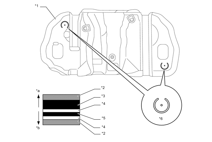
Text in Illustration *1 Fuel Tank Assembly *2 High Density Polyethylene (HDPE) *3 Regrind Material *4 Adhesive *5 Ethylene Vinyl Alcohol Copolymer (EVOH) *6 Fuel Drain Mark *a Fuel Tank Outside *b Fuel Tank Inside -
The fuel tank uses a saddle shape to allow the propeller shaft to pass under the center portion of the tank. Also, a jet pump is used to transfer the fuel from the side of the tank without the fuel pump to the side with the fuel pump.
-
A fuel tank with such a shape tends to cause fuel to be present in both chamber A and chamber B when the fuel level is low. This stops the fuel in chamber B from being pumped out. To prevent this from occurring, a jet pump has been provided to transfer the fuel from chamber B to chamber A.
-
This is accomplished by utilizing the flow of the fuel through the jet pump, so that the pressure difference, which is created by the fuel as it passes through the venturi, is used to suck the fuel out of chamber B and send it to chamber A.
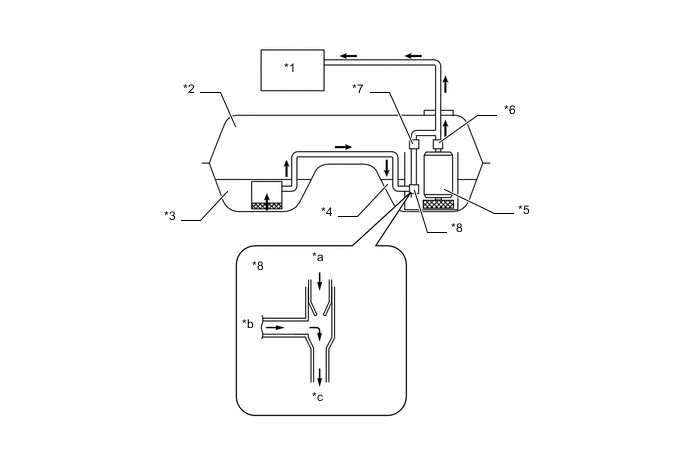
Text in Illustration *1 Engine *2 Fuel Tank Assembly *3 Chamber B *4 Chamber A *5 Fuel Pump (for Low Pressure) *6 Fuel Filter Assembly *7 Fuel Pressure Regulator Assembly *8 Jet Pump *a From Fuel Pump (Return) *b From Chamber B *c To Chamber A - -
-
-
-
OPERATION
-
Fuel Pump Assembly (for High Pressure)
-
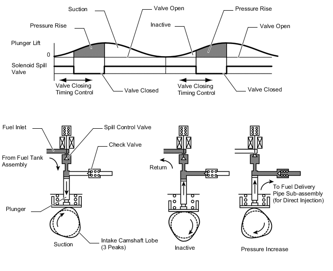
During the intake portion of the pump cycle, the spill control valve is opened, and the pump plunger (piston) is moved downward by spring force. This allows fuel to be drawn into the cylinder of the pump. If the spill control valve has not been closed yet, when the cam forces the plunger to move upward, the fuel in the pump cylinder (this fuel is not pressurized) will be pushed back to the pump inlet (fuel tank side).
-
In order to close the spill control valve as the piston is moving upward, the ECM sends a signal to the valve via the injector driver (EDU). When the spill control valve is closed and the plunger is moving upward, the pressure in the pump cylinder will rise. As this pressure rises above 60 kPa (or the pressure of the delivery pipe, whichever is higher), the fuel will begin to flow to the fuel delivery pipe sub-assembly (for direct injection). The ECM calculates the target fuel pressure based on driving conditions. The ECM controls the pressure by operating the spill control valve via the injector driver (EDU). The timing and duration of the spill control valve closing are varied to cause the pump pressure to meet the target pressure.
-
-