AUDIO AND VISUAL SYSTEM(for Radio Receiver Type) Illumination Circuit
| DTC Code | DTC Name |
|---|---|
| Illumination Circuit |
DESCRIPTION
Power is supplied to the radio receiver assembly and steering pad switch assembly illumination when the light control switch is in the tail or head position.
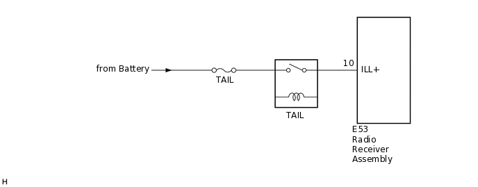
WIRING DIAGRAM
CAUTION / NOTICE / HINT
Inspect the fuses for circuits related to this system before performing the following procedure.
PROCEDURE
CHECK ILLUMINATION
Check if the illumination for the radio receiver assembly, heater control switch or others (hazard switch, transmission control switch, etc.) comes on when the light control switch is turned to the head or tail position.
Result
Result
Proceed to
Illumination comes on for all components except radio receiver assembly.
A
No illumination comes on (radio receiver assembly, hazard switch, heater control switch, etc.).
B
CHECK HARNESS AND CONNECTOR (ILLUMINATION SIGNAL)
Disconnect the E53 radio receiver assembly connector.
Measure the voltage according to the value(s) in the table below.
Standard Voltage
Tester Connection
Condition
Specified Condition
E53-10 (ILL+) - Body ground
Light control switch in tail or head position
11 to 14 V
Result
Proceed to
OK
NG
NG REPAIR OR REPLACE HARNESS OR CONNECTOR