БЛОК СЦЕПЛЕНИЯ (для моделей с 5L-E) СНЯТИЕ
-
DISCONNECT CABLE FROM NEGATIVE BATTERY TERMINAL
CAUTION:
Wait at least 90 seconds after disconnecting the cable from the negative (-) battery terminal to prevent airbag and seat belt pretensioner activation.
-
REMOVE NO. 1 ENGINE COVER SUB-ASSEMBLY (4WD)
-
REMOVE NO. 2 ENGINE COVER SUB-ASSEMBLY (4WD)
-
REMOVE FRONT PROPELLER SHAFT ASSEMBLY (4WD)
-
Remove the front propeller shaft Click here.
-
-
REMOVE REAR PROPELLER SHAFT ASSEMBLY
-
Remove the rear propeller shaft Click here.
-
-
REMOVE MANUAL TRANSMISSION UNIT ASSEMBLY
-
Remove the manual transmission unit.
G58 manual transmission Click here.
G58F manual transmission Click here.
-
-
REMOVE CLUTCH RELEASE BEARING ASSEMBLY
-
REMOVE CLUTCH RELEASE FORK BOOT
-
REMOVE CLUTCH RELEASE FORK SUB-ASSEMBLY
-
REMOVE RELEASE BEARING HUB CLIP
-
REMOVE RELEASE FORK SUPPORT
-
Remove the release fork support from the manual transmission unit.
-
-
REMOVE CLUTCH COVER ASSEMBLY
-
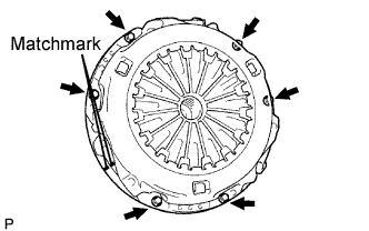
Place matchmarks on the clutch cover and flywheel.
-
Loosen each set bolt 1 turn at a time until spring tension is released.
-
Remove the 6 set bolts and pull off the clutch cover.
Note
Do not drop the clutch disc.
-
-
REMOVE CLUTCH DISC ASSEMBLY
Note
Keep the lining part of the clutch disc, pressure plate and surface of the flywheel away from oil and foreign matter.
-
INSPECT INPUT SHAFT FRONT BEARING
-
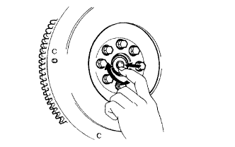
Turn the bearing by hand by applying rotational force.
If the bearing sticks or has much resistance, replace the input shaft bearing.
Tech Tips
The bearing is permanently lubricated and requires no cleaning or lubrication.
-
-
REMOVE INPUT SHAFT FRONT BEARING
-
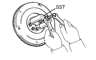
Remove any 2 diametrically opposite bolts.
-
Using SST, remove the input shaft bearing.
- SST
- 09303-35011
-
-
INSPECT CLUTCH DISC ASSEMBLY
-
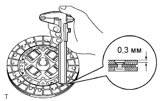
Using a vernier caliper, measure the rivet head depth.
Minimum rivet depth 0.3 mm (0.012 in) If the depth is less than the minimum, replace the clutch disc assembly.
-
Install the clutch disc to the transmission unit.
Note
Be careful not to insert the clutch disc facing the wrong direction.
-
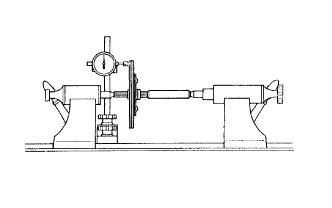
Using a dial indicator, check the disc runout.
Maximum runout 0.8 mm (0.031 in.) If the runout is greater than the maximum, replace the clutch disc assembly.
-
-
INSPECT CLUTCH COVER ASSEMBLY
-
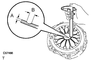
Using a vernier caliper, measure the depth and width of the worn areas of the diaphragm spring.
Maximum depth and width Measurement Specified Condition A (Depth) 0.5 mm (0.020 in.) B (Width) 6.0 mm (0.236 in.) If the depth or width is greater than the maximum, replace the clutch cover assembly.
-
-
INSPECT FLYWHEEL SUB-ASSEMBLY
-
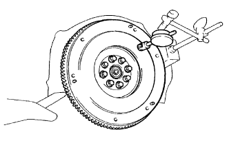
Using a dial indicator, measure the flywheel runout.
Maximum runout 0.1 mm (0.004 in.) If the runout is greater than the maximum, replace the flywheel sub-assembly.
-
-
INSPECT CLUTCH RELEASE BEARING ASSEMBLY
-
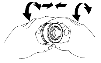
Turn the bearing by hand while applying force in the axial direction.
If the bearing sticks or has much resistance, replace the release bearing.
Tech Tips
The bearing is permanently lubricated and requires no cleaning or lubrication.
-