ДВИГАТЕЛЬ В СБОРЕ СНЯТИЕ
-
DISCHARGE FUEL SYSTEM PRESSURE
CAUTION:
-
Do not disconnect any part of the fuel system until you have discharged the fuel system pressure.
-
Even after discharging the fuel pressure, place a cloth or equivalent over fittings as you separate them to reduce risk of fuel spray on yourself or in the engine compartment.
-
Disconnect the cable from the negative (-) battery terminal.
CAUTION:
Wait at least 90 seconds after disconnecting the cable from the negative (-) battery terminal to prevent airbag and seat belt pretensioner activation.
-
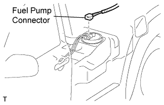
Disconnect the fuel pump connector.
-
Connect the cable to the negative (-) battery terminal.
-
Start the engine. After the engine has stopped on its own, turn the ignition switch OFF.
Tech Tips
DTC P0171/25 (system too lean) may be set.
-
Crank the engine again, then check that the engine does not start.
-
Loosen the fuel tank cap, then discharge the pressure in the fuel tank completely.
-
Connect the fuel pump connector.
-
-
DISCONNECT CABLE FROM NEGATIVE BATTERY TERMINAL
CAUTION:
Wait at least 90 seconds after disconnecting the cable from the negative (-) battery terminal to prevent airbag and seat belt pretensioner activation.
-
REMOVE NO. 1 ENGINE UNDER COVER
-
Remove the 4 bolts and under cover.
-
-
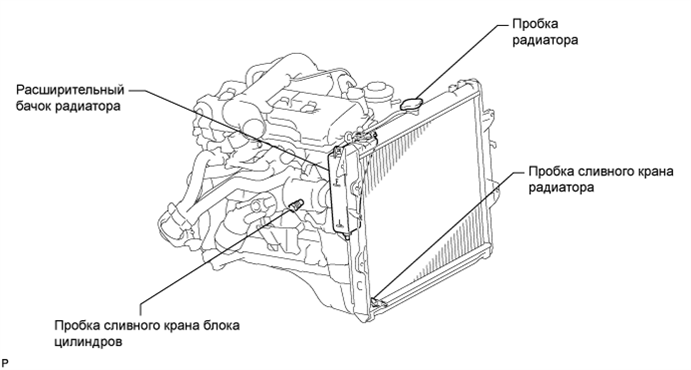
DRAIN ENGINE COOLANT
-
Remove the radiator cap.
-
Loosen the cylinder block drain cock plug and radiator drain cock plug, and then drain the coolant.
Tech Tips
Collect the coolant in a container and dispose of it according to the regulations in your area.
-
-
DRAIN ENGINE OIL
-
Remove the oil filler cap.
-
Remove the oil drain plug and drain the oil into a container.
-
-
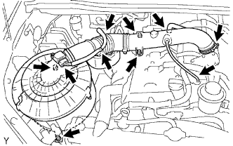
REMOVE INTAKE AIR CONNECTOR AND AIR CLEANER ASSEMBLY
-
Disconnect the vacuum hose.
-
Disconnect the No. 2 ventilation hose.
-
Disconnect the MAF meter connector and wire harness clamps.
-
Loosen the hose clamp and remove the 4 bolts, air cleaner and intake air connector assembly.
-
-
REMOVE RADIATOR GRILLE
-
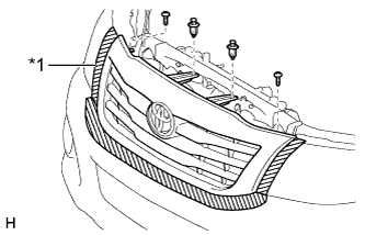
Обозначения на рисунке *1 Защитная клейкая лента Наклейте защитную клейкую ленту вокруг решетки радиатора.
-
Выверните 2 винта и освободите 2 фиксатора.
-
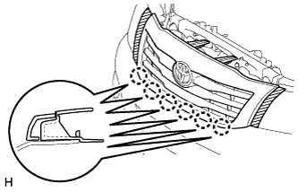
Расцепите 6 захватов и снимите решетку радиатора.
-
-
DISCONNECT RADIATOR INLET HOSE
-
DISCONNECT RADIATOR OUTLET HOSE
-
REMOVE DRIVE BELT
-
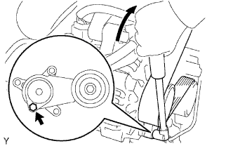
С помощью шестигранника, указанного на рисунке стрелкой, сдвиньте шкив натяжителя вниз, уменьшив тем самым натяжение приводного ремня. Затем снимите приводной ремень.
Note
При снятии приводного ремня не следует использовать болт натяжного шкива.
Tech Tips
После снятия приводного ремня переместите натяжитель вверх, насколько это возможно.
-
-
REMOVE FAN SHROUD
-
Disconnect the reservoir hose from the radiator tank upper.
-
Loosen the 4 nuts holding the fluid coupling fan.
-
Remove the driver belt Click here.
-
Remove the 2 bolts holding the fan shroud.
-
Remove the 4 nuts of the fluid coupling fan, and then remove the shroud together with the coupling fan.
Note
Be careful not to damage the radiator core.
-
Remove the fan pulley from the water pump.
-
-
REMOVE FAN PULLEY
-
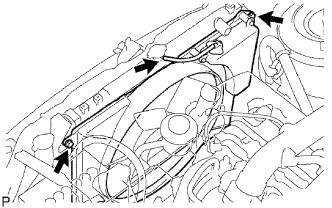
REMOVE RADIATOR ASSEMBLY
-

Disconnect the 2 airbag sensor front connectors.
-
Using a clip remover, detach the 4 clamps from the radiator side as shown in the illustration.
Tech Tips
Tape the clip remover tip before use.
-

Remove the 4 bolts and radiator.
-
-
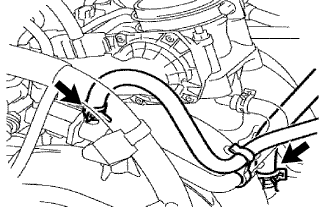
DISCONNECT HOSE
-
Disconnect the vacuum hose (from brake master cylinder).
-
Disconnect the hose from the VSV for EVAP.
-
-
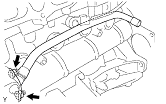
DISCONNECT FUEL HOSE
-
Disconnect the No. 2 fuel hose from the pressure regulator.
-
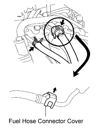
Disconnect the No. 1 fuel hose from the pulsation damper.
-
Detach the lock claw by lifting up the cover, as shown in the illustration.
-
Check for foreign matter on the pipe and around the connector before disconnecting. Clean if necessary.
-
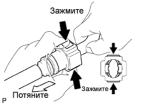
If the connector and the pipe are stuck, pinch the connector, push and pull the pipe to disconnect them.
Note
Do not use any tools in this procedure.
-
Check for foreign matter on the seal surface of the disconnected pipe. Clean if necessary.
-
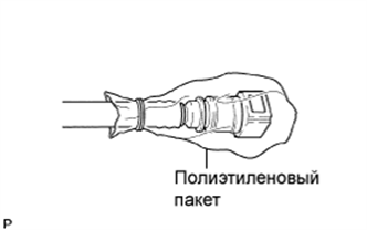
To protect the disconnected pipe and connector from damage and contamination, cover it with a plastic bag.
-
-
-
DISCONNECT ENGINE WIRE
-
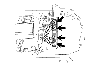
Disconnect the ECM connectors from the cabin.
-
Remove the glove compartment door.
-
Disconnect the 4 ECM connectors.
-
-
Remove the bolt and clamp, and disconnect the ground wire.
-
Remove the bolt and disconnect the ground wire from the frame.
-
Pull out the engine wire from the cabin.
-
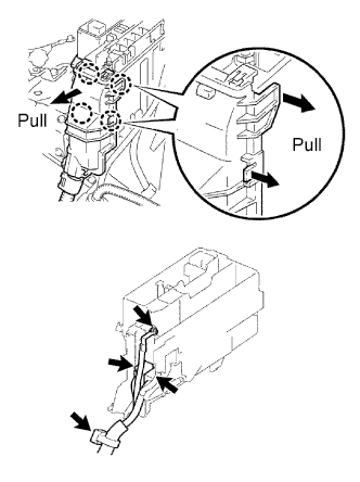
Remove the engine room relay block cover (upper).
-
Remove the engine room relay block cover (side).
-
Using a screwdriver, detach the 4 claws and remove the relay block cover.
Tech Tips
Tape the screwdriver tip before use.
-
-
Remove the nut and disconnect the cable from the engine room junction block.
-
Disconnect the 2 engine room junction block connectors and disconnect the wire clamp.
-
Remove the bolt and disconnect the wire clamp from the front engine mounting bracket LH.
-
Remove the bolt and disconnect the heated oxygen sensor connector from the clamp.
-
-
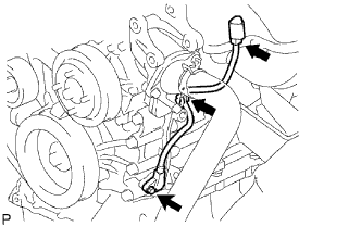
DISCONNECT VANE PUMP
-
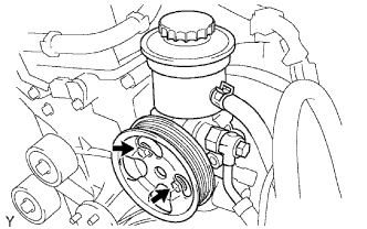
Disconnect the oil pressure switch connector.
-
Remove the 2 bolts and disconnect the vane pump from the engine.
-
Support the vane pump securely.
-
-
REMOVE OIL DIPSTICK
-
REMOVE OIL DIPSTICK GUIDE
-
Remove the bolt, guide and O-ring.
Tech Tips
Cover the gauge guide hole to prevent foreign matter from entering it.
-
-
DISCONNECT COOLER COMPRESSOR (w/ Air Conditioning System)
-
Disconnect the compressor connector.
-
Remove the 2 bolts and disconnect the suction hose from the engine.
-
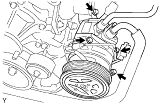
Remove the 4 bolts and disconnect the compressor from the engine.
-
Support the cooler compressor securely.
-
-
REMOVE HOOD ASSEMBLY
-
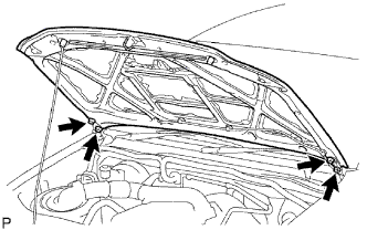
Disconnect the washer nozzle hose.
-
Remove the 4 bolts and hood.
Note
Be careful not to damage the vehicle.
-
-
REMOVE FRONT EXHAUST PIPE
-
Remove the 2 bolts and 2 compression springs.
-
Disconnect the front pipe from the exhaust manifold and remove the gasket.
-
Remove the front pipe from the pipe support.
-
-
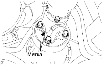
REMOVE PROPELLER SHAFT WITH CENTER BEARING ASSEMBLY
-
Нанесите метки на фланец карданного вала и фланец дифференциала.
-
Отверните 4 гайки, выверните 4 болта, снимите 4 шайбы и отсоедините карданный вал.
-
Выверните 2 установочных болта центрального опорного подшипника и снимите 2 пластины с поперечины рамы.
-
Извлеките карданный вал.
-
Установите SST в удлинитель картера трансмиссии, чтобы не вытекло масло.
- SST
- 09325-40010
-
-
REMOVE STARTER
-
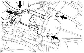
Disconnect the starter connector.
-
Disconnect the terminal cap.
-
Remove the nut and disconnect the starter wire.
-
Remove the 2 bolts and starter.
-
-
REMOVE CLUTCH RELEASE CYLINDER
-
Remove the 2 bolts and disconnect the release cylinder assembly.
-
-
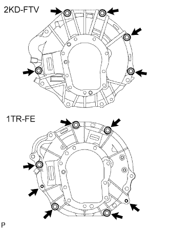
REMOVE MANUAL TRANSMISSION UNIT ASSEMBLY
-
Using a transmission jack, support the transmission.
-
Remove the support stand from the rear side.
-
2KD-FTV:
Remove the 5 bolts and transmission.
-
1TR-FE:
Remove the 7 bolts and transmission.
-
-
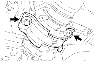
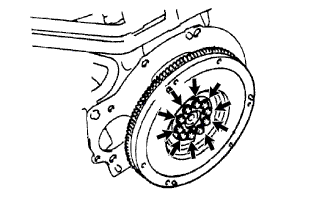
REMOVE CLUTCH COVER
-
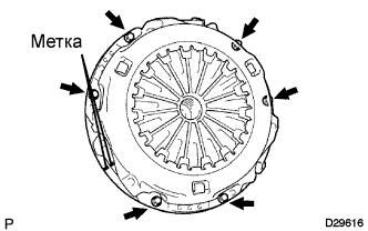
Нанесите метки на кожух сцепления и маховик.
-
Ослабьте все установочные болты, поочередно выворачивая их на один оборот, пока не ослабнет натяжение пружины.
-
Выверните 6 установочных болтов и снимите кожух сцепления.
Note
Будьте осторожны, не уроните ведомый диск сцепления.
-
-
REMOVE CLUTCH DISC
Note
Не допускайте попадания масла и посторонних частиц на фрикционную накладку ведомого диска сцепления, нажимного диска сцепления и поверхность маховика.
-
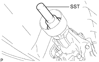
REMOVE FLYWHEEL
-
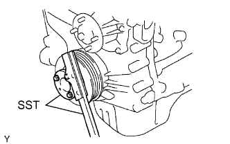
Fix the crankshaft in place with SST.
- SST
- 09213-54015 ( 91651-60855 )
- 09330-00021
-
Remove the 10 bolts and flywheel.
-
-
REMOVE REAR END PLATE
-
Remove the bolt and rear end plate.
-
-
REMOVE ENGINE ASSEMBLY
-
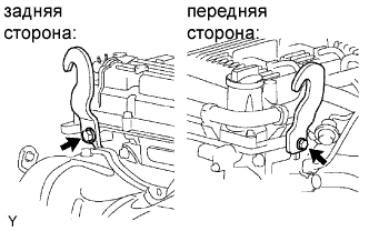
Install the 2 engine hangers as shown in the illustration.
Item Part No. Engine hanger 12281-0C010 Bolt 90105-T0129 - Torque:
- 42 N*m { 428 kgf*cm, 31 ft.*lbf }
-
Attach the engine sling device to the engine hangers.
-
Remove the 4 bolts and 4 nuts and chain block holding the engine mounting bracket and frame.
-
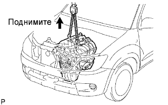
Lift the engine out of the vehicle slowly and carefully.
Note
Make sure to disconnect all the wires, hoses and cables from the engine. Keep the disconnected wires, hoses and cables off of the engine.
-
-
INSTALL ENGINE TO ENGINE STAND
-
Place the engine assembly onto the stand.
-
-
REMOVE IGNITION COIL
-
Disconnect the 4 ignition coil connectors and remove the 4 bolts and 4 ignition coils.
-
-
REMOVE SPARK PLUG
-
REMOVE VENTILATION PIPE
-
Remove the bolt and ventilation pipe.
-
-
REMOVE GENERATOR
-
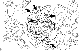
Remove the nut, bolt and generator wire.
-
Disconnect the generator connector.
-
Remove the 2 bolts and generator.
-
-
REMOVE ENGINE WIRE
-
Disconnect the oil pressure sensor connector.
-
Disconnect the noise filter connector.
-
Disconnect the camshaft position sensor connector.
-
Disconnect the 4 injector connectors.
-
Disconnect the crankshaft position sensor connector.
-
Disconnect the OCV connector.
-
Disconnect the throttle body connector.
-
Disconnect the ECT sensor connector.
-
Disconnect the knock sensor connector.
-
Disconnect the wire harness from the clamps.
-
Remove the 2 bolts and wire harness from the engine.
-
-
REMOVE THROTTLE BODY
-
Отсоедините датчик положения дроссельной заслонки и разъем электродвигателя привода.
-
Отсоедините 2 перепускных шланга охлаждающей жидкости.
-
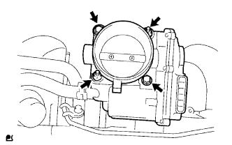
Выверните 2 болта, отверните 2 гайки и снимите корпус дроссельной заслонки.
-
Снимите прокладку.
-
-
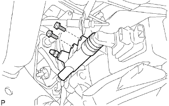
REMOVE FUEL DELIVERY PIPE
CAUTION:
Be careful not to drop the injectors when removing the delivery pipe.
-
Disconnect the 4 clamps and wire harness from the delivery pipe.
-
Disconnect the vacuum hose.
-
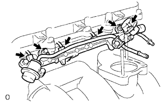
Disconnect the 4 injector connectors.
-
Remove the 2 bolts and delivery pipe together with the 4 injectors.
-
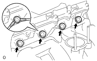
Using 2 screwdrivers, pry out the 4 spacers from the cylinder head.
Tech Tips
Tape the screwdriver tips before use.
-
-
REMOVE INJECTOR
-
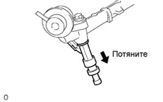
Pull out the 4 injectors from the delivery pipe.
-
-
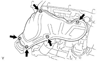
REMOVE INTAKE MANIFOLD
-
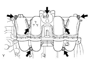
Disconnect the crankshaft position sensor from the clamp.
-
Remove the 5 bolts, 2 nuts, intake manifold and gasket.
-
-
REMOVE EXHAUST MANIFOLD HEAT INSULATOR
-
Remove the 5 bolts and heat insulator.
-
-
REMOVE EXHAUST MANIFOLD
-
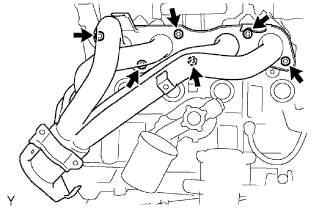
Remove the 6 nuts, exhaust manifold and gasket.
-
-
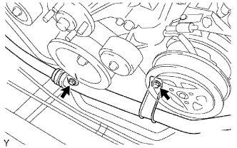
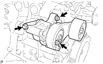
REMOVE IDLE PULLEY ASSEMBLY (w/ Air Conditioning System)
-
Loosen the bolt, and then remove the idle pulley assembly.
Tech Tips
The bolt in the illustration cannot be removed from the idle pulley assembly.
-
-
REMOVE NO. 1 COMPRESSOR MOUNTING BRACKET (w/ Air Conditioning System)
-
Remove the 5 bolts and No. 1 compressor mounting bracket.
-
-
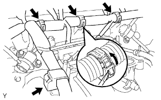
REMOVE V-RIBBED BELT TENSIONER
-
Remove the 3 bolts and belt tensioner.
-
-
REMOVE WATER INLET
-
Remove the bolt, 2 nuts, water inlet and gasket.
-
-
REMOVE THERMOSTAT
-
Remove the thermostat and gasket.
-
-
REMOVE NO. 1 IDLER PULLEY
-
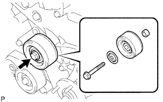
Remove the bolt, pulley plate, idler pulley and spacer.
-
-
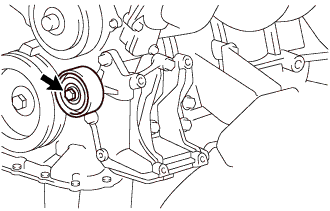
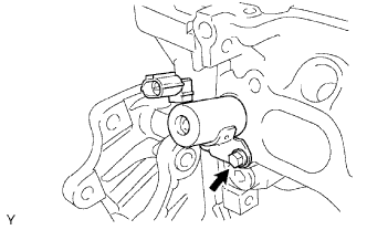
REMOVE OIL PRESSURE SWITCH
-
Using a 24 mm deep socket wrench, remove the oil pressure switch.
-
-
REMOVE NO. 1 WATER BY-PASS PIPE
-
Remove the 2 nuts, water by-pass pipe and gasket.
-
-
REMOVE KNOCK SENSOR
-
Remove the bolt and sensor.
-
-
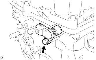
REMOVE ENGINE COOLANT TEMPERATURE SENSOR
-
Using a 19 mm deep socket wrench, remove the sensor.
-
-
REMOVE CAMSHAFT POSITION SENSOR
-
Remove the bolt, sensor and O-ring.
-
-
REMOVE CRANKSHAFT POSITION SENSOR
-
Disconnect the sensor connector.
-
Disconnect the connector from the connector bracket.
-
Detach the harness clamp.
-
Remove the bolt and sensor.
-
-
REMOVE CAMSHAFT TIMING OIL CONTROL VALVE
-
Remove the bolt, oil control valve and O-ring.
-
-
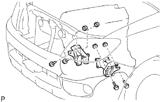
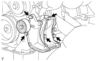
REMOVE FRONT ENGINE MOUNTING BRACKET RH
-
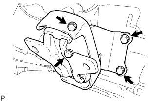
Remove the 4 bolts and mounting bracket.
-
-
REMOVE FRONT ENGINE MOUNTING BRACKET LH
-
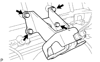
Remove the 4 bolts and mounting bracket.
-