ТОПЛИВНЫЙ НАСОС СНЯТИЕ
CAUTION / NOTICE / HINT
The necessary procedures (adjustment, calibration, initialization, or registration) that must be performed after parts are removed, installed, or replaced during the fuel pump removal/installation are shown below.
| Replacement Part or Procedure | Necessary Procedures | Effects/Inoperative when not Performed | Link |
|---|---|---|---|
| Battery terminal is disconnected/reconnected | Drive the vehicle until stop and start control is permitted (approximately 5 to 60 minutes) | Stop and start system | |
| Memorize steering angle neutral point | Panoramic view monitor system | ||
| Initialize back door lock | Power door lock control system | ||
| Initialize servo motor | Air conditioning system | ||
| Reset slide door close position | Power slide door system | ||
| Reset back door close position | Power back door system | ||
| Replacement of fuel pump | Inspection After Repair |
|
PROCEDURE
-
PRECAUTION
Note
After turning the engine switch off, waiting time may be required before disconnecting the cable from the negative (-) battery terminal. Therefore, make sure to read the disconnecting the cable from the negative (-) battery terminal notices before proceeding with work.
-
DISCHARGE FUEL SYSTEM PRESSURE
-
DISCONNECT CABLE FROM NEGATIVE BATTERY TERMINAL
Note
When disconnecting the cable, some systems need to be initialized after the cable is reconnected.
-
REMOVE SEAT TRACK LOWER RAIL PROTECTOR
-
REMOVE REAR FLOOR SERVICE HOLE COVER
-
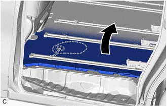
Turn back the rear floor mat assembly.
-
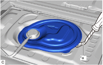
*a Protective Tape Using a clip remover with its tip wrapped with protective tape, remove the rear floor service hole cover and butyl tape.
-
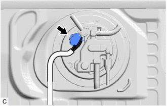
Disconnect the fuel pump connector.
-
-
DISCONNECT CHARCOAL CANISTER OUTLET TUBE SUB-ASSEMBLY
-
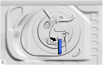
Disconnect the charcoal canister outlet tube sub-assembly from the fuel suction tube with pump and gauge assembly.
-
-
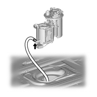
DISCONNECT NO. 1 FUEL EVAPORATION TUBE SUB-ASSEMBLY
-
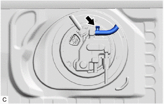
Slide the clip and disconnect the No. 1 fuel evaporation tube sub-assembly from the fuel suction tube with pump and gauge assembly.
-
-
DISCONNECT NO. 2 FUEL EVAPORATION TUBE SUB-ASSEMBLY
Note
Remove any foreign matter on the fuel tube connector and fuel pipe before performing this work.
-
Disconnect the No. 2 fuel evaporation tube sub-assembly from the fuel suction tube with pump and gauge assembly.
-
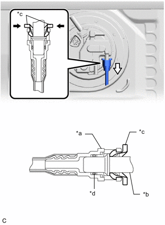
*a Fuel Tube Connector *b Fuel Pipe *c Retainer *d O-ring 
Pinch 
Pull Pinch the retainer of the fuel tube connector, and then pull the fuel tube connector off of the fuel pipe.
Note
Be sure to disconnect the fuel tube connector by hand.
-
If the fuel tube connector and fuel pipe are stuck, push and pull the fuel tube connector to release it. Pull the fuel tube connector off of the fuel pipe carefully.
Note
-
Be sure to disconnect the fuel tube connector by hand.
-
Do not scratch or allow any foreign matter to get on the parts when disconnecting them as the fuel tube connector has an O-ring that seals the pipe (fuel pipe).
-
-
Check that there is no foreign matter on the sealing surfaces of the disconnected fuel lines. Clean them if necessary.
-
Cover the disconnected fuel pipe and fuel tube connector with plastic bags to prevent damage and contamination.
-
-
-
DISCONNECT FUEL TANK MAIN TUBE SUB-ASSEMBLY
-
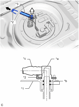
*1 Fuel Suction Plate Sub-assembly *2 Tube Joint Clip *3 Fuel Tank Main Tube Sub-assembly *a Fuel Tube Joint *b O-ring *c Nylon Tube Pull off Pull off Remove the tube joint clip, and pull off the fuel tube joint of the fuel tank main tube sub-assembly.
Note
-
Remove any foreign matter on the fuel tube joint before performing this work.
-
Do not scratch or allow any foreign matter to get on the parts when disconnecting them as the fuel tube connector has O-rings that seal the pipe (fuel pipe).
-
Be sure to disconnect the fuel tube joint by hand.
-
Do not bend, twist, pinch or kink the nylon tube.
-
Protect the disconnected part by covering it with a plastic bag after disconnecting the fuel tube joint.
-
If the fuel tube joint and fuel suction plate sub-assembly are stuck, push and pull to release them.
-
-
-
REMOVE FUEL TANK VENT TUBE SET PLATE
-
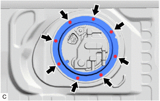
Remove the 8 bolts and fuel tank vent tube set plate.
-
-
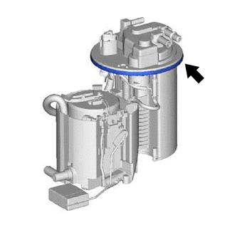
REMOVE FUEL SUCTION TUBE WITH PUMP AND GAUGE ASSEMBLY
-
Remove the fuel suction tube with pump and gauge assembly from the fuel tank assembly.
-
Slide the clip and disconnect the fuel return vent tube sub-assembly from the fuel suction tube with pump and gauge assembly.
Note
-
Do not bend, twist, pinch or kink the fuel return vent tube sub-assembly.
-
Be careful not to bend the arm of the fuel sender gauge assembly.
-
Do not damage the fuel pump harness.
-
Do not apply excessive force to the fuel suction tube with pump and gauge assembly.
-
-
Remove the fuel suction tube set gasket from the fuel suction tube with pump and gauge assembly.
-