SHIFT LEVER REASSEMBLY
PROCEDURE
-
INSTALL FLOOR SHIFT CONNECTING ROD SWIVEL
-
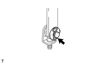
Install the 2 washers, grommet, pin and floor shift connecting rod swivel to the select lever with the clip.
-
-
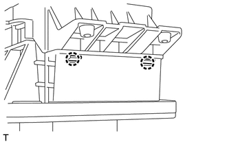
INSTALL SHIFT LEVER SEAT SUB-ASSEMBLY
-

Install the shift lever seat sub-assembly and the 4 spacer plates to the base plate.
-
-
INSTALL FLOOR SHIFT SUPPORT BRACKET
-
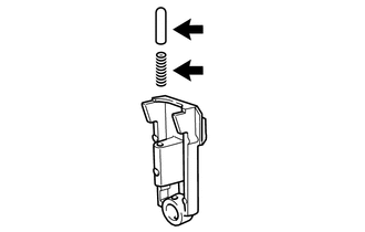
Apply MP grease to the spring and pin.
-
Install the spring and pin to the floor shift support bracket.
-
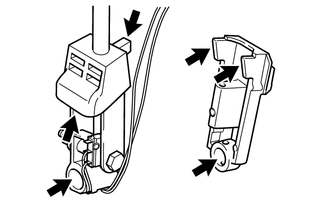
Apply MP grease to the floor shift control shaft lever and floor shift support bracket.
-
Install the floor shift support bracket to the floor shift control shaft lever.
-
-
INSTALL FLOOR SHIFT CONTROL SELECT LEVER
-
Install the floor shift support bracket and floor shift control shaft lever to the base plate.
-
-
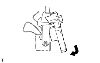
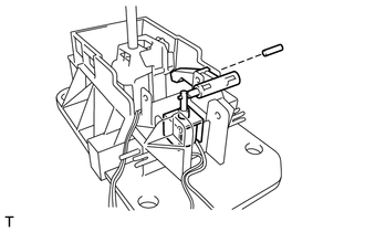
INSTALL FLOOR SHIFT CONTROL SHAFT LEVER
-
Install the floor shift control shaft lever to the base plate.
-
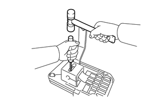
Using a pin punch (3 mm (0.118 in.)) and a hammer, install a new spring pin.
-
-
INSTALL SHIFT LEVER PLATE GROMMET
-
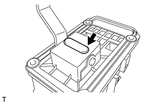
Install the shift lever plate grommet to the base plate.
-
-
INSTALL DETENT ROD
-
Install the bush detent lock.
-
Install the cushion detent lock to the detent lock rod.
-
Apply MP grease to the detent lock spring and detent lock rod.
-
Install the detent lock rod and detent lock spring.
-
Install the detent lock clamp.
-
-
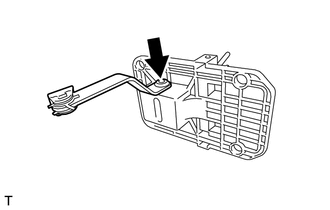
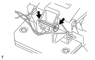
INSTALL SHIFT LOCK CONTROL UNIT ASSEMBLY
-
Apply MP grease to the pin.
-
Install the shift lock release arm to the shift lock control unit assembly.
-
Install the shift lock control unit assembly to the base plate.
-
-
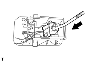
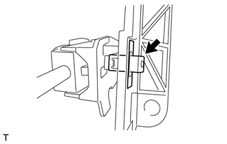
INSTALL FLOOR SHIFT SHIFT LEVER HOUSING
-
Engage the 2 claws and install the floor shift shift lever housing to the base plate.
-
Install the shift lever lock nut and shift lever lock pin.
-
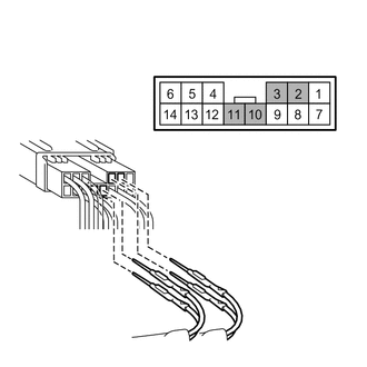
Install the terminals 2, 3, 10 and 11 of the transmission control switch connector.
-
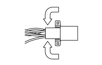
Lock the harness connector terminals.
-
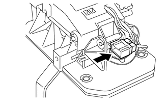
Engage the claw and install the connector.
-