WIRELESS DOOR LOCK CONTROL SYSTEM(w/o Entry and Start System) Only Wireless Control Function is Inoperative
| DTC Code | DTC Name |
|---|---|
| Only Wireless Control Function is Inoperative |
DESCRIPTION
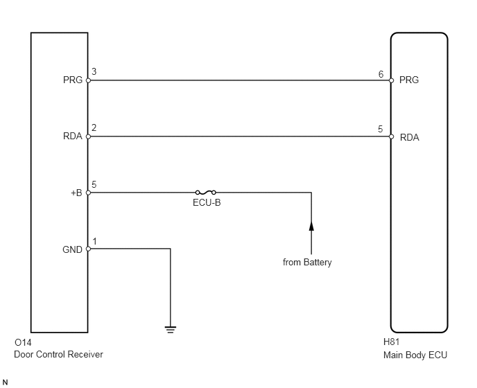
The door control receiver receives signals from the transmitter and sends these signals to the main body ECU. The main body ECU then controls all the doors by sending lock/unlock signals to each door.
WIRING DIAGRAM
CAUTION / NOTICE / HINT
Inspect the fuses for circuits related to this system before performing the following inspection procedure.
As the door control battery is installed between the vehicle battery and main body ECU (instrument panel junction block assembly), first perform the inspections in On-Vehicle Inspection to confirm that there are no malfunctions in the power source circuit for the main body ECU (instrument panel junction block assembly) before performing this troubleshooting procedure (Click here).
PROCEDURE
CHECK POWER DOOR LOCK OPERATION
Check the power door lock operation (Click here).
OK
Each door locks and unlocks normally.
CHECK KEY REMINDER WARNING OPERATION
Check the key reminder buzzer operation (Click here).
Tip:If the key reminder buzzer is functioning normally, it can be assumed that the unlock warning switch is also functioning normally.
OK
Key reminder buzzer operates normally.
CHECK WIRELESS DOOR CONTROL TRANSMITTER
Check whether the wireless door lock control functions operate normally with another registered transmitter.
OK
Wireless door lock control functions operate normally.
CHECK FOR ELECTRICAL NOISEClick here
CHECK TRANSMITTER BATTERY
Remove the battery from the inoperative wireless door control transmitter (Click here).
Measure the voltage according to the value(s) in the table below.
Standard Voltage
Tester Connection
Condition
Specified Condition
Battery positive (+) - Battery negative (-)
Always
2.5 to 3.2 V
REPLACE DOOR CONTROL TRANSMITTER
CHECK FOR ELECTRICAL NOISE
Move the transmitter in the vicinity of the door control receiver.
Tip:Refer to Parts Location for the location of the door control receiver (Click here).
Press and hold either the lock or unlock transmitter switch for 1 second, and check that the doors are locked or unlocked accordingly.
OK
Wireless door lock control functions operate normally.
Tip:Check if electrical noise is the cause by moving the door control transmitter closer to the door control receiver. Moving closer will decrease the effects of electrical noise.
If the operation check can be performed normally, there is a high probability that electrical noise or a decrease in output from the door control transmitter is the cause of the malfunction. There is a high probability that electrical noise is the cause if the problem occurs only in a certain location or only during a certain time of day. Also, custom components may be causing electrical noise. If custom components are installed in the vehicle, remove them and perform the operation check again.
FIND CAUSE OF ELECTRICAL NOISE AND REMOVE IT
CHECK HARNESS AND CONNECTOR (MAIN BODY ECU - DOOR CONTROL RECEIVER)
-
Disconnect the H81 ECU connector.
Disconnect the O14 receiver connector.
Measure the resistance according to the value(s) in the table below.
Standard Resistance
Tester Connection
Condition
Specified Condition
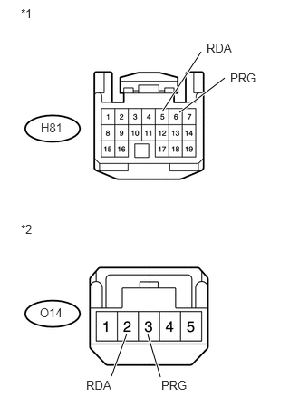
H81-5 (RDA) - O14-2 (RDA)
Always
Below 1 Ω
H81-6 (PRG) - O14-3 (PRG)
H81-5 (RDA) or O14-2 (RDA) - Body ground
Always
10 kΩ or higher
H81-6 (PRG) or O14-3 (PRG) - Body ground
Table 1. Text in Illustration *1
Front view of wire harness connector
(to Main Body ECU)
*2
Front view of wire harness connector
(to Door Control Receiver)
REPAIR OR REPLACE HARNESS OR CONNECTOR
-
CHECK HARNESS AND CONNECTOR (DOOR CONTROL RECEIVER - BATTERY AND BODY GROUND)
-
Disconnect the O14 receiver connector.
Measure the resistance and voltage according to the value(s) in the table below.
Standard Resistance
Tester Connection
Condition
Specified Condition
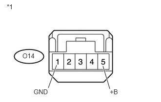
O14-1 (GND) - Body ground
Always
Below 1 Ω
Standard Voltage
Tester Connection
Condition
Specified Condition
O14-5 (+B) - Body ground
Always
11 to 14 V
Table 2. Text in Illustration *1
Front view of wire harness connector
(to Door Control Receiver)
REPAIR OR REPLACE HARNESS OR CONNECTOR
-
CHECK DOOR CONTROL RECEIVER (OUTPUT)
-
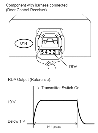
Measure the voltage according to the value(s) in the table below.
Standard Voltage
Tester Connection
Tool Setting
Switch Condition
Specified Condition
O14-2 (RDA) - Body ground
10 V/DIV., 50 μsec./DIV.
No key in ignition key cylinder, all doors closed and transmitter switch off → on
Pulse generation
OK
Door control receiver outputs a pulse.
REPLACE MAIN BODY ECU (INSTRUMENT PANEL JUNCTION BLOCK ASSEMBLY)
-