ECD SYSTEM, Diagnostic DTC:P0101
| DTC Code | DTC Name |
|---|---|
| P0101 | Mass or Volume Air Flow Sensor "A" Circuit Range / Performance |
DESCRIPTION
Refer to DTC P0102.
DTC No. |
Detection Item |
DTC Detection Condition |
Trouble Area |
MIL |
Memory |
|---|---|---|---|---|---|
P0101 |
Mass or Volume Air Flow Sensor "A" Circuit Range / Performance |
When difference between mass air flow meter sub-assembly reading and estimated MAF exceeds threshold. (3 trip detection logic) |
|
Comes on |
DTC stored |
DTC No. |
Data List |
|---|---|
P0101 |
|
WIRING DIAGRAM
Refer to DTC P0102.
CAUTION / NOTICE / HINT
When replacing the ECM, the ECM needs registration and initialization.
After replacing the mass air flow meter sub-assembly, the ECM needs initialization.
After replacing the swirl control valve, the ECM needs initialization.
Inspect the fuses for circuits related to this system before performing the following inspection procedure.
When the ECM must be replaced, before replacing the ECM, perform the "Learning V alues Save" function using the GTS. Then after installing the new ECM, perform all of the initialization/registrations for the "Learning Values Write" function by following the instructions shown on the GTS display.
Read freeze frame data using the GTS. Freeze frame data records the engine condition when malfunctions are detected. When troubleshooting, freeze frame data can help determine if the vehicle was moving or stationary, if the engine was warmed up or not, and other data from the time the malfunction occurred.
PROCEDURE
READ VALUE USING GTS (INTAKE AIR AND INTAKE AIR TEMP (TURBO))
Connect the GTS to the DLC3.
Turn the ignition switch to ON and turn the GTS on.
Enter the following menus: Powertrain / Engine and ECT / Data List / Intake Air and Intake Air Temp (Turbo).
Powertrain > Engine and ECT > Data List
Tester Display
Intake Air
Intake Air Temp (Turbo)
Start the engine and wait 30 seconds.
Read the value.
OK
Difference between Intake Air and Intake Air Temp (Turbo) is 25°C (45°F) or less.
Result
Proceed to
OK
NG
NG REPLACE INTAKE AIR TEMPERATURE SENSORClick here
CHECK HARNESS AND CONNECTOR (MASS AIR FLOW METER SUB-ASSEMBLY - ECM)
Disconnect the mass air flow meter sub-assembly connector.
Disconnect the ECM connector.
Measure the resistance according to the value(s) in the table below.
Standard Resistance
Tester Connection
Condition
Specified Condition
B113-5 (VG) - B112-97 (VG)
Always
Below 1 Ω
B113-4 (VGR) - B112-98 (VGR)
Always
Below 1 Ω
B113-2 (E2G) - B112-129 (EVG)
Always
Below 1 Ω
B113-5 (VG) or B112-97 (VG) - Body ground
Always
10 kΩ or higher
B113-4 (VGR) or B112-98 (VGR) - Body ground
Always
10 kΩ or higher
B113-2 (E2G) or B112-129 (EVG) - Body ground
Always
10 kΩ or higher
Result
Proceed to
OK
NG
NG REPAIR OR REPLACE HARNESS OR CONNECTOR (MASS AIR FLOW METER SUB-ASSEMBLY - EFI MAIN NO. 1 RELAY OR ECM POWER SOURCE CIRCUIT)Click here
CHECK HARNESS AND CONNECTOR (POWER SOURCE)
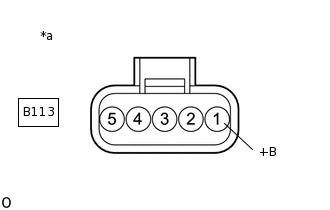
*a
Front view of wire harness connector
(to Mass Air Flow Meter Sub-assembly)
Disconnect the mass air flow meter sub-assembly connector.
Turn the ignition switch to ON.
Measure the voltage according to the value(s) in the table below.
Standard Voltage
Tester Connection
Switch Condition
Specified Condition
B113-1 (+B) - Body ground
Ignition switch ON
11 to 14 V
Result
Proceed to
OK
NG
NG REPAIR OR REPLACE HARNESS OR CONNECTOR (MASS AIR FLOW METER SUB-ASSEMBLY - EFI MAIN NO. 1 RELAY OR ECM POWER SOURCE CIRCUIT)Click here
CHECK INTAKE SYSTEM
Start the engine.
Check air duct between intake silencer, mass air flow meter sub-assembly and turbocharger for leaks.
Check air duct between turbocharger and intake manifold for leaks.
Tip:Oily patches are signs of leaks.
Check whether sealing rings on charge air hoses are rolled back or missing.
OK
No leakage.
Result
Proceed to
OK
NG
NG REPAIR OR REPLACE INTAKE SYSTEMClick here
CHECK AIR CLEANER FILTER ELEMENT SUB-ASSEMBLY
Inspect the air cleaner filter element sub-assembly.
OK
No blockage in air cleaner filter element sub-assembly.
Result
Proceed to
OK
NG
NG REPLACE AIR CLEANER FILTER ELEMENT SUB-ASSEMBLYClick here
CHECK EGR VALVE ASSEMBLY
Check that the there is no catching in the EGR valve assembly and installed parts have not been excessively tightened.
Check for DTCs related to the EGR valve assembly.
OK
There is no catching in the EGR valve assembly, installed parts have not been excessively tightened and no DTCs are stored.
Result
Proceed to
OK
NG
NG REPAIR OR REPLACE EGR VALVE ASSEMBLYClick here
CHECK SWIRL CONTROL VALVE
Check operation of swirl flaps and fault code memory entries.
OK
DTCs are not stored and function operates normally.
Result
Proceed to
OK
NG
NG REPLACE SWIRL CONTROL VALVEClick here
CHECK DIESEL THROTTLE BODY ASSEMBLY
Check for DTCs related to the diesel throttle body assembly function.
OK
DTCs are not stored and function operates normally.
Result
Proceed to
OK
NG
NG REPAIR OR REPLACE DIESEL THROTTLE BODY ASSEMBLYClick here
CHECK INTAKE PORT AND INTAKE VALVES
Check intake ports and intake valves for coking.
Tip:Excessive oil loss from crankcase ventilation system can cause coking, especially when in the case of short-distance driving.
OK
Intake ports and intake valves are not coked.
Result
Proceed to
OK
NG
NG CLEAN INTAKE PORT AND INTAKE VALVESClick here
REPLACE MASS AIR FLOW METER SUB-ASSEMBLY
Replace the mass air flow meter sub-assembly.
Perform the mass air flow meter sub-assembly learning value reset.
Result
Proceed to
NEXT
CHECK WHETHER DTC OUTPUT RECURS (DTC P0101)
Connect the GTS to the DLC3.
Turn the ignition switch to ON and turn the GTS on.
Clear the DTCs.
Powertrain > Engine and ECT > Clear DTCs
Turn the ignition switch off and wait for 60 seconds or more [A].
Perform road test [B].
Repeat [A] and [B] for the number of trips detected.
Enter the following menus: Powertrain / Engine and ECT / Trouble Codes.
Powertrain > Engine and ECT > Trouble Codes
Read the DTCs.
Result
Result
Result
Proceed to
No DTC output
No DTC output
A
DTC P0101
DTC P0101
B
A END
REPLACE ECM
Replace the ECM.
Result
Proceed to
NEXT
NEXT CONFIRM WHETHER MALFUNCTION HAS BEEN SUCCESSFULLY REPAIREDClick here
CLEAN INTAKE PORT AND INTAKE VALVES
Clean coke from the intake ports and intake valves.
Result
Proceed to
NEXT
NEXT CONFIRM WHETHER MALFUNCTION HAS BEEN SUCCESSFULLY REPAIREDClick here
REPAIR OR REPLACE DIESEL THROTTLE BODY ASSEMBLY
Repair or replace diesel throttle body assembly or perform inspections and troubleshooting for related DTCs.
Result
Proceed to
NEXT
NEXT CONFIRM WHETHER MALFUNCTION HAS BEEN SUCCESSFULLY REPAIREDClick here
REPLACE SWIRL CONTROL VALVE
Replace the swirl control valve.
Perform the swirl valve learning value reset.
Result
Proceed to
NEXT
NEXT CONFIRM WHETHER MALFUNCTION HAS BEEN SUCCESSFULLY REPAIREDClick here
REPAIR OR REPLACE EGR VALVE ASSEMBLY
Repair or replace EGR valve assembly or perform inspections and troubleshooting for related DTCs.
Tip:When the EGR valve assembly is replaced, perform initialization.
Result
Proceed to
NEXT
NEXT CONFIRM WHETHER MALFUNCTION HAS BEEN SUCCESSFULLY REPAIREDClick here
REPLACE AIR CLEANER FILTER ELEMENT SUB-ASSEMBLY
Replace the air cleaner filter element sub-assembly.
Result
Proceed to
NEXT
NEXT CONFIRM WHETHER MALFUNCTION HAS BEEN SUCCESSFULLY REPAIREDClick here
REPAIR OR REPLACE INTAKE SYSTEM
Repair or replace the malfunctioning parts of the intake system.
Result
Proceed to
NEXT
NEXT CONFIRM WHETHER MALFUNCTION HAS BEEN SUCCESSFULLY REPAIREDClick here
REPAIR OR REPLACE HARNESS OR CONNECTOR (MASS AIR FLOW METER SUB-ASSEMBLY - EFI MAIN NO. 1 RELAY OR ECM POWER SOURCE CIRCUIT)
Repair or replace the harness or connector.
Result
Proceed to
NEXT
NEXT CONFIRM WHETHER MALFUNCTION HAS BEEN SUCCESSFULLY REPAIREDClick here
REPLACE INTAKE AIR TEMPERATURE SENSOR
Replace the intake air temperature sensor.
Result
Proceed to
NEXT
CONFIRM WHETHER MALFUNCTION HAS BEEN SUCCESSFULLY REPAIRED
Connect the GTS to the DLC3.
Turn the ignition switch to ON and turn the GTS on.
Clear the DTCs.
Powertrain > Engine and ECT > Clear DTCs
Turn the ignition switch off and wait for 60 seconds or more [A].
Perform road test [B].
Repeat [A] and [B] for the number of trips detected.
Enter the following menus: Powertrain / Engine and ECT / Trouble Codes.
Powertrain > Engine and ECT > Trouble Codes
Confirm that the DTC is not output again.
Result
Proceed to
NEXT
NEXT END