BODY STRUCTURE
-
FUNCTION
-
Impact Absorbing Structure for Front Collisions
-
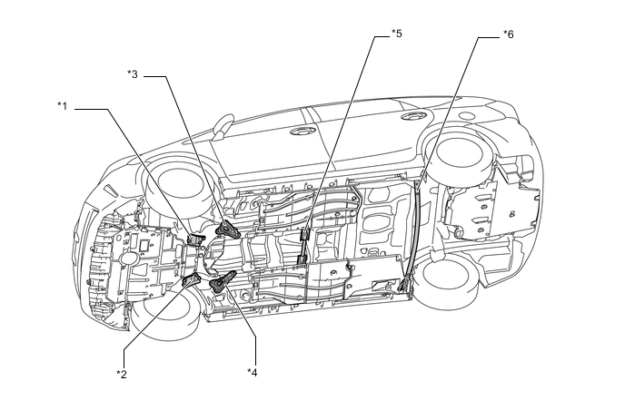
The front side members utilize high strength sheet steel in a construction that absorbs and disperses energy in a frontal collision.
-
The use of under members enables a construction that disperses load from the radiator supports.
-
Door beltline reinforcements have been strengthened to optimize dispersal of collision energy to the rails, door beltline, and rocker panel.
-
The use of a cross member in the dash panel enables a construction that disperses load from the front side members to the floor member and upper body.
-
The use of members on the front floor at the sides of the tunnel enables a construction that achieves tunnel strength and dispersal of load from the front side members.
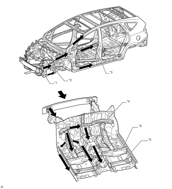
Text in Illustration *1 Under Member *2 Front Side Member *3 Front Door Beltline Reinforcement *4 Cross Member of the Dash Panel (Front Panel Member Sub-assembly) *5 Member at the Side of the Tunnel - - 
Impact 
Path of Collision Energy -
Impact absorbing pads with sound absorbing performance are installed from the lower surface of the dash panel to the front of the floor as a measure to reduce leg injury in collision.
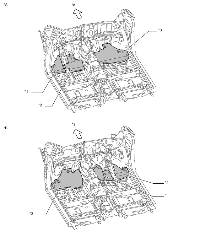
Text in Illustration *A LHD Models *B RHD Models *1 Foot Rest Area (No. 2 Dash Panel Insulator Pad) *2 Accelerator Pedal Area (No. 1 Dash Panel Insulator Pad) *3 Passenger Seat (No. 3 Dash Panel Insulator Pad) - - *a Front - -
-
-
Impact Absorbing Structure for Side Collision
-
Ultra high strength sheet steel is used for the center pillar inner reinforcement and roof center reinforcement to ensure high strength.
-
Bulkheads are placed on both sides of floor cross members to efficiently transmit impact load from the impact beams to the floor cross members.
-
The use of a roof reinforcement enables a construction that transmits load to the opposite side of the vehicle in a collision.
-
Optimal placement of the impact protect beams enables a construction that efficiently transmits load.
-
The impact support box has been optimally placed on the front floor between the front driver's seat and front passenger's seat to ensure that load is transmitted from the center pillar to the seat pipe, impact support box, and seat pipe on the opposite side, thus helping secure passengers space.
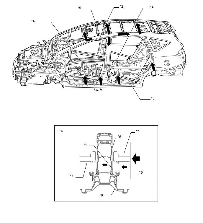
Text in Illustration *1 Impact Support Box *2 Roof Reinforcement *3 Impact Beam *4 Floor Cross Member *5 Center Pillar *6 Center Console Box *7 Front Seat Pipe *8 Front Floor *a A-A Cross Section - - Path of Collision Energy - -
-
-
Impact absorbing pads have been installed on the inside of the front door trim board sub-assembly and rear door trim board sub-assembly, softening the impact to the occupant hip area in a side collision.
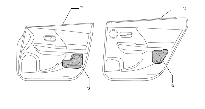
Text in Illustration *1 Front Door Trim Board Sub-assembly *2 Rear Door Trim Board Sub-assembly *3 Impact Absorbing Pad - - -
Impact absorbing materials and cavities have been added to the inner side of each pillar garnish and the headliner in consideration of an occupant's head impacting a pillar or the roof during an accident. If an occupant's head impacts a pillar or the roof, impact energy will be absorbed by the impact absorbing material and the deformation of the ribbed section of the pillar garnishes.
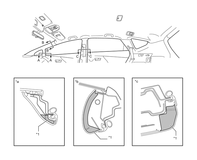
Text in Illustration *1 Impact Absorbing Material - - *a A-A Cross Section *b B-B Cross Section *c C-C Cross Section *d D-D Cross Section -
Impact Absorbing Structure for Rear Collision
-
Rear side members are used to reduce body deformation in a rear collision.
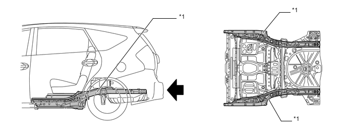
Text in Illustration *1 Rear Side Member - - Path of Collision Energy - -
-
-
Lessening Pedestrian Injury
-
An energy absorber is provided at the front of the front bumper reinforcement to dampen the impact to the legs in the event of a collision with a pedestrian.
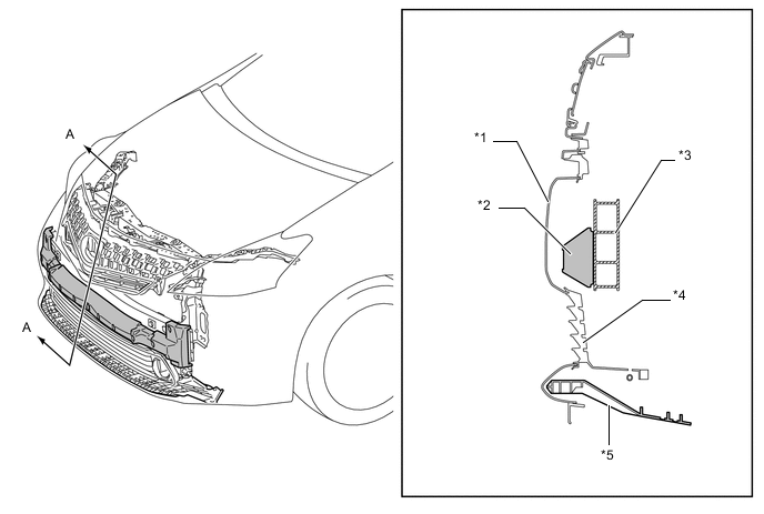
Text in Illustration *1 Front Bumper Cover *2 Front Bumper Energy Absorber *3 Front Bumper Reinforcement *4 Lower Grille *5 Front Lower Bumper Absorber - - *a A-A Cross Section - - -
A longitudinal ribbed structure is adopted for the inner hood to cushion impact.
-
The space between the hood panel and the hood reinforcement lock striker has been formed into a crushable structure so that the hood sub-assembly can collapse easily during a collision.
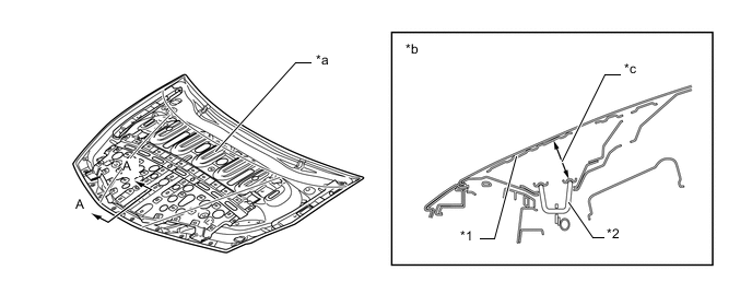
Text in Illustration *1 Hood Reinforcement *2 Hood Lock Striker *a Longitudinal Ribbed Structure *b A-A Cross Section *c Space - - -
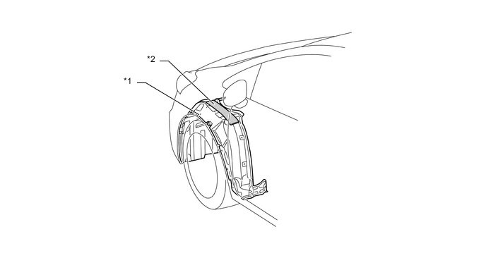
An impact absorbing bracket is used for the mounting portion of the front fender panel to absorb impact energy to the head of the pedestrian in a collision, thus dampening the impact to the head.
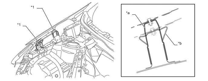
Text in Illustration *1 Impact-absorbing Bracket - - *a Before Collision *b After Collision -
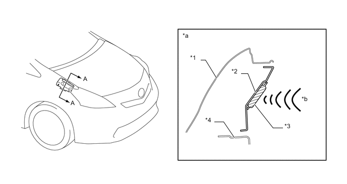
A hood hinge that deforms to absorb energy when impacted from above has been adopted, softening the impact in a collision with a pedestrian.
Text in Illustration *1 Front Fender Panel (Front Fender Sub-assembly RH) *2 Hood Panel Hinge *a A-A Cross Section (Normal) *b A-A Cross Section (After Collision) Impact - - -
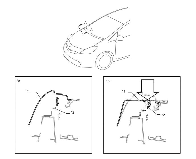
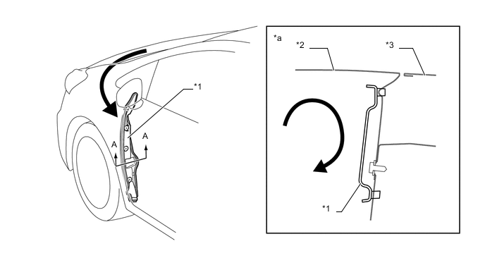
The back of the hood and the cowl use an open section structure that collapses easily in an impact from the top, thus reducing the impact to and head injuries sustained by a pedestrian in an accident.
Text in Illustration *1 Hood Panel *2 Windshield Glass *a A-A Cross Section (Before Collision) *b Open Section Structure (Rear Edge of Hood Panel) *c Open Section Structure (Cowl) *d A-A Cross Section (After Collision) Impact - -
-
-
Aerodynamics
-
The surface where the front pillar meets the windshield has been leveled off, and the shape around the doors and rockers are smoothed to effectively reduce flow separation. As an additional measure to reduce flow separation, an optimized angle has been adopted for the side surfaces of the front bumper.
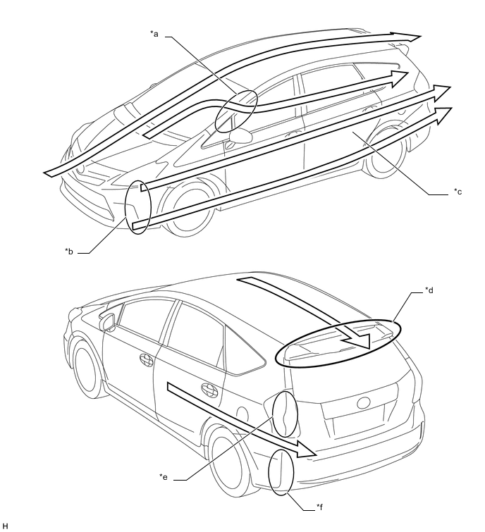
Text in Illustration *a Leveled off Front Pillar to Reduce Turbulence *b Reduced Flow Separation by Optimizing Angle of Side Surface of Front Bumper *c Smooth Flow along Doors and Rocker Surface *d Optimum Length and Angle of Rear Spoiler *e Air-kick Shape on Rear Combination Light *f Sharp Edge at the Side or Rear Bumper Airflow - - -
Spats are fitted at the front of the front and rear tires to direct the air flow, and this reduces air turbulence in the wheel house, helping to ensure straight driving stability at high speeds.
-
The height, angle, and shape of the engine under covers have been optimized, resulting in smooth airflow underneath the floor.
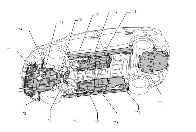
Text in Illustration *1 Front Bumper Absorber Lower *2 No. 1 Engine Under Cover *3 Front No. 2 Engine Under Cover *4 Front Wheel Opening Extension Pad LH (Front Spats) *5 Front Wheel Opening Extension Pad RH (Front Spats) *6 Front No. 3 Engine Under Cover *7 Body Rocker Panel Moulding Assembly LH *8 Body Rocker Panel Moulding Assembly RH *9 Front Floor Cover LH *10 Front Floor Cover RH *11 Front Floor Cover CTR LH *12 Front Floor Cover CTR RH *13 Rear Floor Side Member Cover RH *14 Floor Under No. 2 Cover -
A deflector is installed onto the radiator support to direct driving airflow into the radiator, thus leading to improvement in the ventilation performance of the vehicle front section.
-
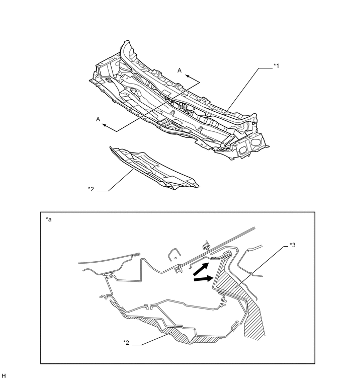
Heater air duct splash shield seals have been added between the cowl top ventilator louver sub-assembly and the cowl top panel, preventing engine compartment heat from affecting the air entering the cabin.
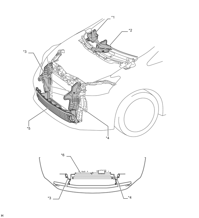
Text in Illustration *1 Heater Air Duct Splash Shield Seal (RH) *2 Heater Air Duct Splash Shield Seal (LH) *3 Radiator Side Deflector RH *4 Radiator Side Deflector LH *5 Lower No. 1 Radiator Grille Lower *6 Cooler Condenser Assembly
-
-
-
CONSTRUCTION
-
Light Weight and Highly Rigid Body
-
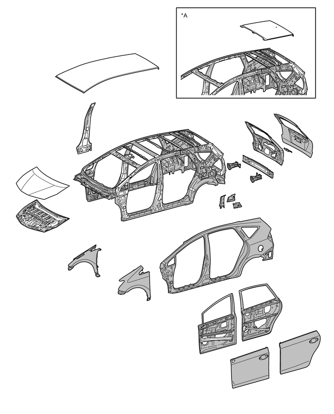
A highly rigid yet lightweight vehicle body has been created by considerable use of mainly high strength sheet steel and ultra high strength sheet steel for body frame members, thus ensuring a high level of impact safety, driving stability and quietness.
-
Aluminum is used in the hood panel and rear bumper reinforcement, resulting in light weight.
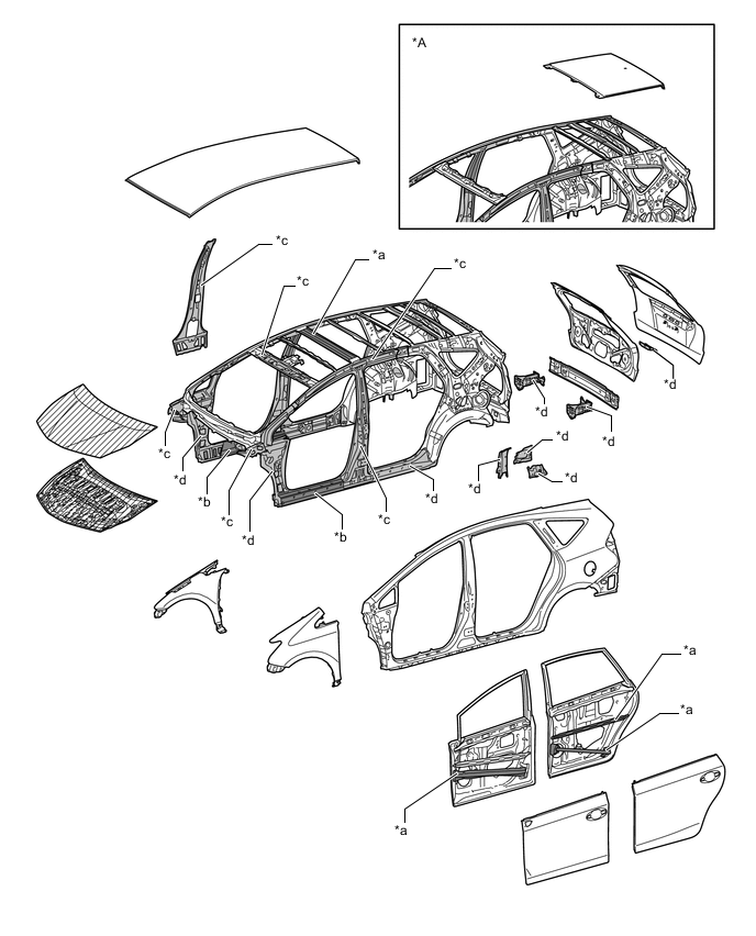
Text in Illustration (Upper Body:) *A Models with Roof Sunshade System - - *a Ultra High Strength Steel (1470 MPa Class) *b High Strength Steel (980 MPa Class) *c High Strength Steel (590 MPa Class) *d High Strength Steel (440 MPa Class) 
Ultra High Strength Sheet Steel 
High Strength Sheet Steel 
Aluminum - - 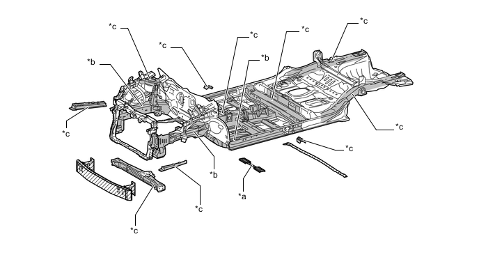
Text in Illustration (Under Body:) *a Ultra High Strength Steel (1470 MPa Class) *b High Strength Steel (590 MPa Class) *c High Strength Steel (440 MPa Class) - - Ultra High Strength Sheet Steel High Strength Sheet Steel Aluminum - -
-
-
Body Shell Construction
-
A brace (front stabilizer bracket) is used on the lower side of the front suspension member to improve front suspension member fore-aft rigidity and ensure excellent driving stability.
-
Braces have been added to the front suspension member rear section, floor tunnel and floor panel end section, ensuring torsional rigidity and excellent handling stability.
Text in Illustration *1 Front Floor Cross Member Reinforcement Sub-assembly LH *2 Front Floor Cross Member Reinforcement Sub-assembly RH *3 Floor Panel Brace Front LH *4 Floor Panel Brace Front RH *5 Front Floor Brace Center *6 Rear Suspension Brace Sub-assembly -
A straight outer cowl top panel sub-assembly is used to connect the left and right front spring supports, improving lateral rigidity and ensuring front suspension input point rigidity and body rigidity.
-
A cowl side reinforcement sub-assembly is used to connect the front spring support and front body inner pillar, resulting in improved rigidity.
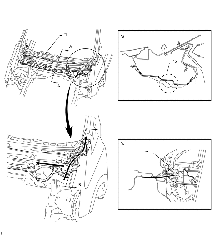
Text in Illustration *1 Outer Cowl Top Panel Sub-assembly *2 Cowl Side Reinforcement Sub-assembly *a A-A Cross Section *b Straight *c B-B Cross Section - - Path of Collision Energy - - -
The entire circumference of the back door opening, from the rear header to the lower back panel uses an open structure, ensuring rigidity for the back door opening.
-
Reinforcements (body lower back panel sub-assembly and body lower back No. 2 reinforcement RH/LH) are used to connect both rear sidemembers and side panels beneath the lower back panel, ensuring rigidity to counter twisting forces and delivering excellent driving stability.
-
An inner gusset (quarter wheel house inner gusset) and outer reinforcement (roof side outer panel) are used for the wheel house construction, ensuring lateral rigidity at the rear absorber mounting portions, thus ensuring rigidity to counter twisting forces and achieving excellent driving stability.
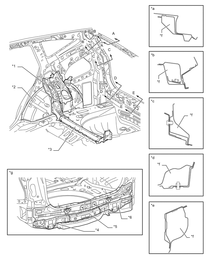
Text in Illustration *1 Quarter Wheel House Gusset Rear RH *2 Quarter Wheel House Panel Sub-assembly RH *3 Rear Floor Pan Reinforcement *4 Body Lower Back No. 2 Reinforcement LH *5 Body Lower Back panel Sub-assembly *6 Body Lower Back No. 2 Reinforcement RH *a A-A Cross Section *b B-B Cross Section *c C-C Cross Section *d D-D Cross Section *e E-E Cross Section *f Open Section Structure *g Rear View - -
-
-
Anti-corrosion Sheet Steel
-
Anti-corrosion sheet steel is used as in the following illustration.
Text in Illustration (Upper Body:) *A Models with Roof Sunshade System - Anti-corrosion Sheet Steel - - 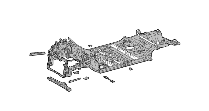
Text in Illustration (Under Body:) Anti-corrosion Sheet Steel - -
-
-
Wax and Sealer
-
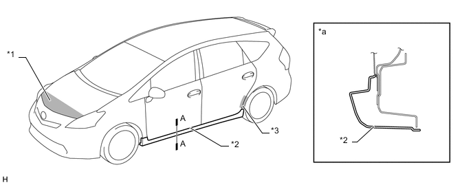
Wax is applied to front edge of the hood, the edge of the lower part of the door, and the fuel filler lid hinge to improve rust-resistance performance. Sealer is applied to hemmed portions of the front edge of a hood, front and back door panels and fuel filler lid.
-
-
Under Coat
-
Acrylic acid resin is applied to the under side of the body, inside the wheel housing and other parts that are susceptible to stone chipping damage, thus improving the rust-resistance performance of these areas.
-
-
Anti-chipping Application
-
To help prevent the paint from chipping, anti-chipping paint is applied to the hood panel.
-
Anti-chipping tape is applied to the quarter panel on the back of the rear door to protect the paint surface from icy snow or gravel and to achieve a high level of rust resistance.
Text in Illustration *1 Soft Chipping Primer *2 Plastic Rocker *3 Anti-chipping Tape - - *a A-A Cross Section - -
-
-
Low Vibration and Low Noise Body
-
A hood insulator is provided on the rear of the hood panel. This achieves excellent sound insulation performance.
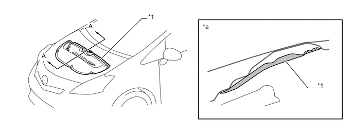
Text in Illustration *1 Hood Insulator - - *a A-A Cross Section - - -
An outer dash panel insulator is provided. This reduces the amount of engine noise leaking into and out of the cabin.
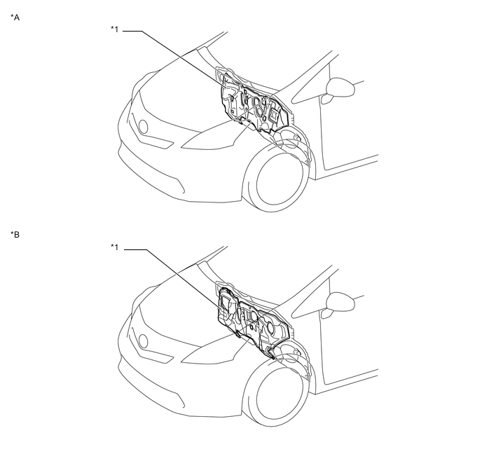
Text in Illustration *A LHD Models *B RHD Models *1 Outer Dash Panel Insulator - - -
The front (engine side) of the cowl top outer front panel uses a cowl top insulator sheet to reduce the amount of engine noise entering the vehicle cabin from the engine compartment.
Text in Illustration *1 Outer Cowl Top Panel Sub-assembly *2 Outer No. 2 Dash Panel Insulator *3 Outer Dash Panel Insulator - - *a A-A Cross Section - - Noise - - -
Sound absorbing material (front fender seal) is used in the front fender liner to reduce road noise.
Text in Illustration *1 Front Fender Liner *2 Sound-absorbing Material (Front Fender Seal) -
A front fender upper protector is used on the engine compartment side of the fender side cover to reduce the amount of noise transmitted from the area between the fender and apron to the vehicle cabin.
Text in Illustration *1 Front Fender *2 Front Upper Fender Protector *3 Sound-absorbing Material *4 Fender Apron *a A-A Cross Section *b Noise -
A front fender side panel protector is used to reduce the amount of noise transmitted from the area between the fender and front pillar to the vehicle cabin.
Text in Illustration *1 Front Fender Side Panel Protector *2 Fender Panel *3 Front Door Panel - - *a A-A Cross Section - - Noise - - -
Foamed urethane sponge, foamed sealing material and sealing material are applied to the roof panel and pillars to reduce wind and road noise.
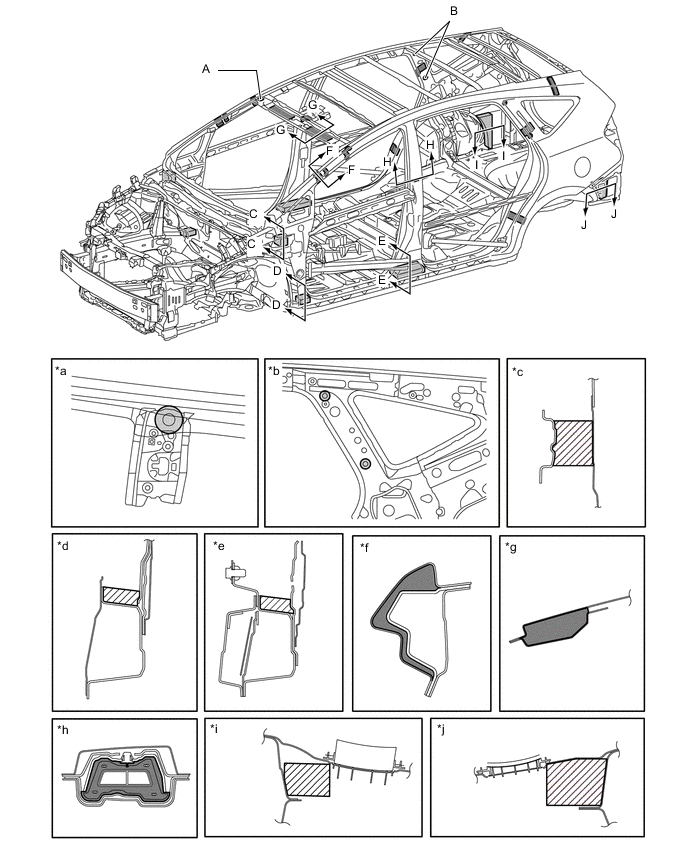
Text in Illustration *a Side View of A *b Side View of B *c C-C Cross Section *d D-D Cross Section *e E-E Cross Section *f F-F Cross Section *g G-G Cross Section *h H-H Cross Section *i I-I Cross Section *j J-J Cross Section Sealing Material Foamed Urethane Sponge Foamed Sealing Material - - -
The following body structures are used in order to reduce panel vibration and body frame movement.
Panel vibration reduction structure
-
The dash panel cross member is provided
-
The tunnel reinforcement is connected to the floor
-
The floor pan panel rigidity has been improved
-
The floor pan bead layouts has been changed
Body frame movement prevention structure
-
Rocker inner bulkheads are provided
-
The rocker inner rear and floor are rigidly connected
-
A straight shape No. 1 cross member is used
Text in Illustration *1 Instrument Panel to Cowl Brace Center *2 Dash Panel Cross Member *3 Tunnel Reinforcement *4 Bead *5 Rocker Inner Bulkhead *6 Rocker Inner Rear *7 No.1 Crossmember - - -
-
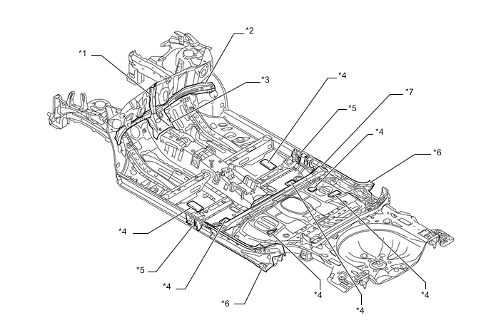
Anti-vibration material is applied to the floor in order to reduce noise in the cabin. As a replacement for the conventional asphalt-based vibration damping sheet, high rigidity spray type damping material is used, thus optimizing material coating thickness. This ensures high quality sound insulation and weight reduction. By applying it also to the vertical part of the dash panel, noise from the engine compartment has been reduced.
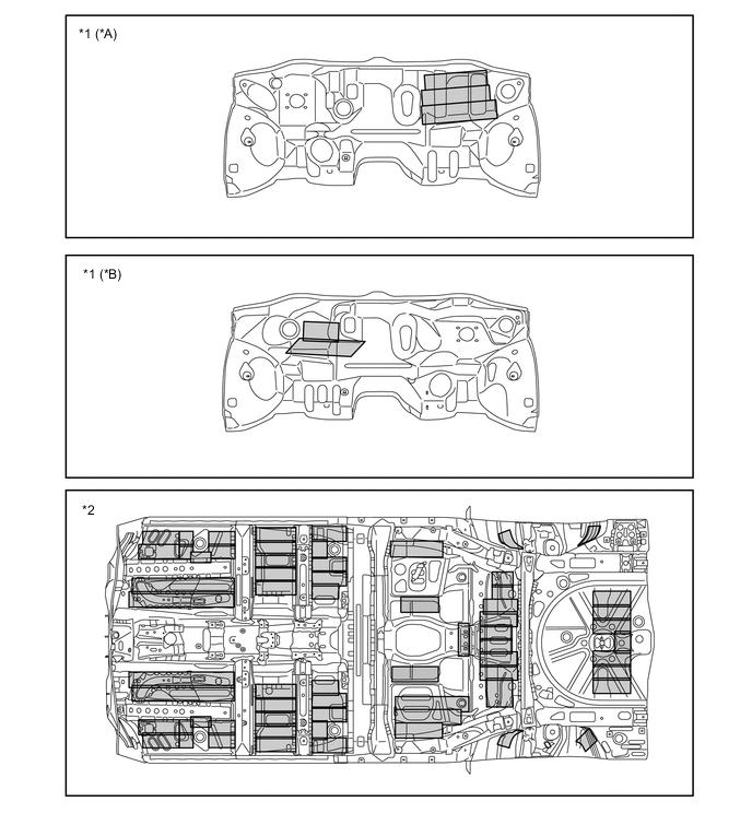
Text in Illustration *A LHD Models *B RHD Models *1 Dash Panel *2 Floor Spray Type Damping Material Application Area - - -
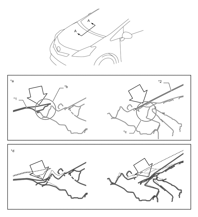
The following part shapes have been changed and the following structure is used for reducing wind noise.
Windshield Area Hood Rear Edge Shape Change
-
The rear edge of the hood is raised to control the airflow to the wipers.
-
An air flow routing plate has been provided to the fender parting section in order to smooth the airflow.
Flush Surface Structure Usage
-
The gap between the windshield glass and the roof has been made smaller to smooth the airflow.
Front Pillar Shape Change
-
The gap between the windshield and the front pillar has been optimized to reduce airflow to the rear.
-
The gap between the frame design surface and the front window fixed moulding has been made smaller.
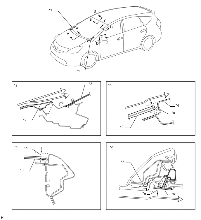
Text in Illustration *1 Air Flow Routing Plate *2 Hood Rear Edge *3 Windshield Glass *4 Roof Panel *5 Frame Design Surface *6 Front Window Fixed Moulding *a A-A Cross Section *b B-B Cross Section *c C-C Cross Section *d D-D Cross Section *e Gap - - Airflow - - Door Window Area Caulking Sponge Usage
-
Caulking sponge has been added to the front end of the beltline molding to suppress whistling sounds from the rear end of the beltline molding.
Front Door Glass Channel
-
A channel has been added to the bottom edge of the door glass, increasing glass rigidity and suppressing the intrusion of road noise.
Black Out Tape and Weatherstrip
-
Blackout tape has been applied to reduce wind noise from the gap between the front door panel and rear door panel.
-
Weatherstrips have been added to the door opening to reduce noise intrusion into the cabin.
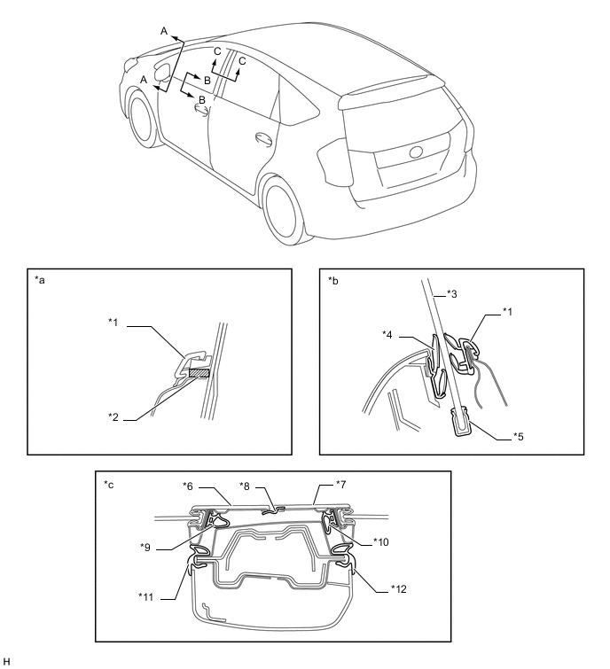
Text in Illustration *1 Front Door Belt Moulding Assembly *2 Caulking Sponge *3 Glass *4 Front Door Glass Weatherstrip Inner *5 Front Door Glass Channel *6 Front Door *7 Rear Door *8 Black Out Tape *9 Front Door Weatherstrip *10 Rear Door Weatherstrip *11 Front Door Opening Trim Weatherstrip *12 Rear Door Opening Trim Weatherstrip *a A-A Cross Section *b B-B Cross Section *c C-C Cross Section - - -
-
-
Parts with Low Repair Cost
-
The front bumper reinforcement crush box (front side member bracket) absorbs impact energy to reduce damage to the body frame. The front bumper reinforcement is connected to the front sidemember using bolts to improve ease of repair and replacement.
-
A structure which connects the radiator support to the front sidemembers using bolts is used to improve the ease of repair, by reducing the damage to related parts (only the damaged parts need to be replaced).
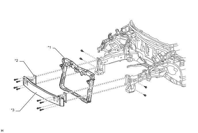
Text in Illustration *1 Radiator Support Sub-assembly *2 Crush Box (Front Side Member Bracket Sub-assembly) *3 Front Bumper Reinforcement Sub-assembly - - -
In case of a minor collision, the radiator support moves rearward together with the cooling unit, thus protecting the cooling unit and reducing damage.
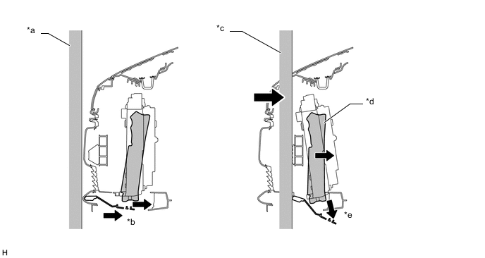
Text in Illustration *a Barrier *b Before Collision *c Barrier Intrusion *d Radiator Support Moves Rearward Together with the Cooling unit *e After Collision - - Collision Energy Load Application Direction - - -
The rear bumper arm sub-assembly is connected to the body lower back panel sub-assembly using bolts to improve the ease of repair and replacement.
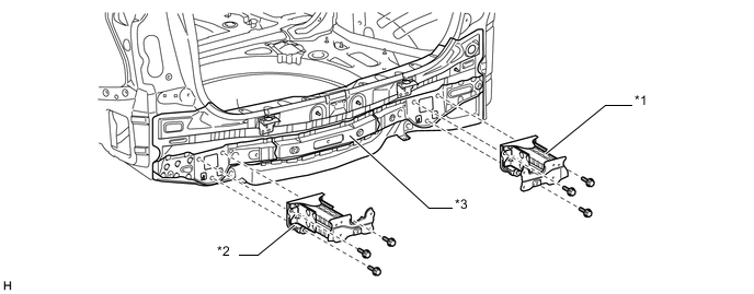
Text in Illustration *1 Rear Bumper Arm Sub-assembly RH *2 Rear Bumper Arm Sub-assembly LH *3 Body Lower Back Panel Sub-assembly - -
-
-