MANUAL TRANSAXLE ASSEMBLY INSTALLATION
PROCEDURE
-
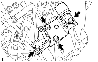
INSTALL REAR ENGINE MOUNTING BRACKET
-
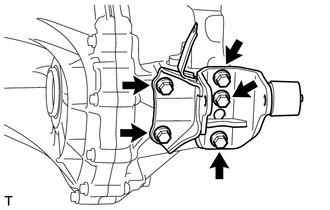
Install the rear engine mounting bracket with the 5 bolts.
- Torque:
- 45 N*m { 459 kgf*cm, 33 ft.*lbf }
-
-
INSTALL FRONT ENGINE MOUNTING BRACKET
-
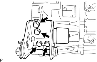
Install the front engine mounting bracket with the 4 bolts.
- Torque:
- 64 N*m { 653 kgf*cm, 47 ft.*lbf }
-
-
INSTALL REAR ENGINE MOUNTING INSULATOR
-
INSTALL MANUAL TRANSAXLE ASSEMBLY
Note
-
Be extremely careful that the body, clutch pipe line and radiator cooling fan do not interfere with the manual transaxle assembly when installing the transaxle.
-
When installing the manual transaxle assembly, it is necessary to move the engine assembly and manual transaxle assembly up and down, and back and forth. Therefore, continually confirm that the parts are properly supported and stable while performing this step.
-
Make sure that the dowel pins are not loose, bent, damaged or scratched.
-
While adjusting the angle of the transmission jack raise the manual transaxle assembly until it is in line with the engine assembly.
Note
Be careful that the clutch pipe line does not interfere with the manual transaxle assembly.
-
Adjust the height and angle of the transmission jack, align the input shaft with the clutch disc, and then install the manual transaxle assembly to the engine with the contact surfaces of the engine and transaxle flat against each other.
-
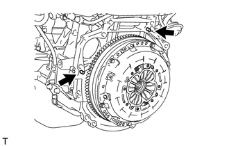
Temporarily install the manual transaxle assembly with the 6 bolts.
Note
Before tightening the bolts, insert the dowel pins into the dowel holes securely so that the end face of the transaxle assembly fits close against the engine assembly.
-
Apply adhesive to the 4 bolts.
Adhesive Toyota Genuine Adhesive 1324, Three Bond 1324 or equivalent -
Install the engine mounting bracket LH with the 4 bolts.
- Torque:
- 64 N*m { 653 kgf*cm, 47 ft.*lbf }
-
Install the 4 bolts and engine mount insulator LH.
- Torque:
- 95 N*m { 969 kgf*cm, 70 ft.*lbf }
-
Slowly raise the engine assembly and transmission assembly using a transmission jack, and then align the installation positions of the engine mounting insulator LH and engine mount bracket LH.
-
Install the nut and through bolt, and then connect the engine mounting insulator LH to the engine mount bracket LH.
- Torque:
- 56 N*m { 571 kgf*cm, 41 ft.*lbf }
-
-
INSTALL NO. 2 MANIFOLD STAY
-
Temporarily install the No. 2 manifold stay with the 2 bolts and nut.
-
-
INSTALL STARTER ASSEMBLY
-
Temporarily install the starter assembly with the 2 bolts.
-
-
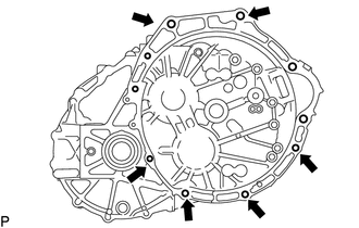
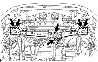
TIGHTEN ENGINE AND TRANSAXLE CONNECTING BOLT
-
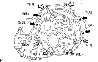
Tighten the 10 bolts in the sequence shown in the illustration.
- Torque:
- Bolt A
- 64 N*m { 653 kgf*cm, 47 ft.*lbf }
- Bolt B
- 79 N*m { 806 kgf*cm, 58 ft.*lbf }
- Bolt C
- 64 N*m { 653 kgf*cm, 47 ft.*lbf }
- Bolt D
- 24 N*m { 245 kgf*cm, 18 ft.*lbf }
Text in Illustration 
E14 "TORX" bolt
Bolt length 100 mm (3.94 in.)

E14 "TORX" bolt
Bolt length 80 mm (3.15 in.)

Hexagon Bolt
Bolt length 40 mm (1.57 in.)
-
Tighten the nut of the No. 2 manifold stay.
- Torque:
- 21 N*m { 218 kgf*cm, 16 ft.*lbf }
-
-
INSTALL FRONT ENGINE MOUNTING INSULATOR
-
Install the front engine mounting insulator with the through bolt and nut.
- Torque:
- 145 N*m { 1479 kgf*cm, 107 ft.*lbf }
-
-
INSTALL FRONT CROSSMEMBER SUB-ASSEMBLY
-
Install the front crossmember sub-assembly with the 6 bolts.
- Torque:
- for bolt A
- 99 N*m { 1010 kgf*cm, 73 ft.*lbf }
- for bolt B
- 95 N*m { 969 kgf*cm, 70 ft.*lbf }
-
Remove the transmission jack.
-
-
INSTALL FRONT SUSPENSION MEMBER
-
INSTALL ENGINE WIRE
-
Connect the ground cable with the bolt.
- Torque:
- 13 N*m { 130 kgf*cm, 9 ft.*lbf }
-
Connect the back-up light switch connector, neutral position switch connector and 2 bolts.
- Torque:
- 13 N*m { 130 kgf*cm, 9 ft.*lbf }
-
-
CONNECT CLUTCH RELEASE CYLINDER ASSEMBLY
-
INSTALL NO. 1 CLUTCH HOUSING COVER
-
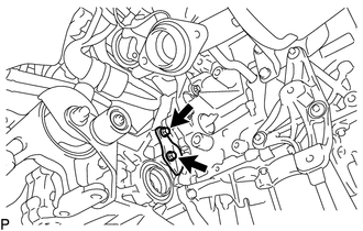
Install the No. 1 clutch housing cover with the 2 bolts.
- Torque:
- 30 N*m { 306 kgf*cm, 22 ft.*lbf }
-
-
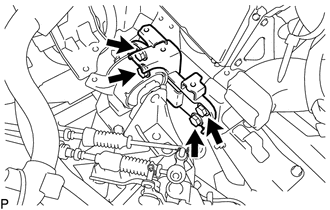
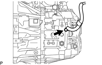
CONNECT TRANSMISSION CONTROL CABLE ASSEMBLY
-
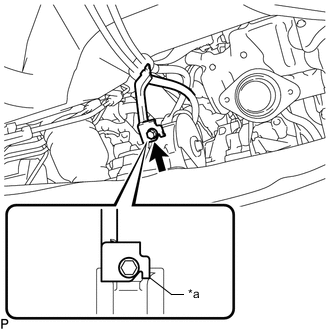
Text in Illustration *a Anti-rotation Pin Connect the bracket of the transmission control cable assembly with the bolt.
- Torque:
- 5.0 N*m { 51 kgf*cm, 44 in.*lbf }
Tech Tips
Make sure the anti-rotation pin is contacting the rear engine mount insulator.
-
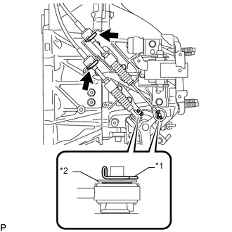
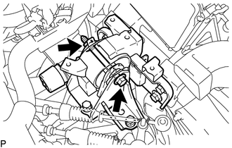
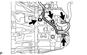
Text in Illustration *1 Clip *2 Metal Washer Plate Connect the 2 cables to the control cable bracket with 2 new clips.
Note
Do not bend the cable more than necessary.
-
Connect the 2 cables to the manual transaxle assembly and install the 2 clips.
Tech Tips
Make sure that the metal washer plate of the shift cable is facing toward the outside of the vehicle.
-
-
INSTALL NO. 1 AIR TUBE ASSEMBLY
-
CONNECT INTERCOOLER AIR HOSE
-
CONNECT COMPRESSOR OUTLET ELBOW
-
INSTALL NO. 4 WATER BY-PASS HOSE
-
CONNECT WIRE HARNESS
-
INSTALL AIR CLEANER BRACKET
-
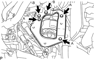
Install the air cleaner bracket with the 5 bolts.
- Torque:
- for Bolt A
- 7.0 N*m { 71 kgf*cm, 62 in.*lbf }
- for Bolt B
- 18 N*m { 178 kgf*cm, 13 ft.*lbf }
-
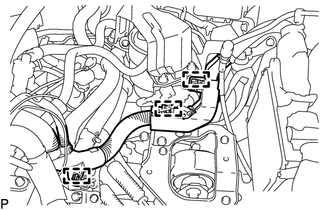
Connect the wire harness with the 3 clamps.
-
-
INSTALL AIR CLEANER CASE SUB-ASSEMBLY
-
INSTALL AIR CLEANER FILTER ELEMENT SUB-ASSEMBLY
-
INSTALL AIR CLEANER CAP SUB-ASSEMBLY WITH AIR CLEANER HOSE ASSEMBLY
-
INSTALL DRIVE SHAFT ASSEMBLY
-
INSTALL STARTER ASSEMBLY
-
INSTALL EXHAUST PIPE ASSEMBLY
-
INSTALL OUTER COWL TOP PANEL
-
INSTALL FRONT WIPER MOTOR AND LINK ASSEMBLY
-
ADD ENGINE COOLANT
-
ADD MANUAL TRANSAXLE OIL
-
FOR COOLANT LEAK
-
INSPECT FOR OIL LEAK
-
CONNECT CABLE TO NEGATIVE BATTERY TERMINAL
Note
When disconnecting the cable, some systems need to be initialized after the cable is reconnected Click here.
-
INSPECT FOR EXHAUST GAS LEAK
-
INSTALL REAR ENGINE UNDER COVER LH
-
INSTALL REAR ENGINE UNDER COVER RH
-
INSTALL NO. 2 ENGINE UNDER COVER
-
INSTALL NO. 1 ENGINE UNDER COVER
-
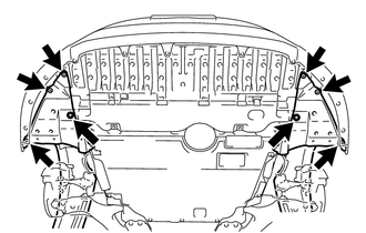
INSTALL FRONT LOWER BUMPER ABSORBER
-
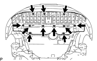
Install the front lower bumper absorber with the 8 bolts and 3 screws.
-
Install the 6 screws and 2 bolts.
-
-
INSTALL NO. 1 ENGINE COVER