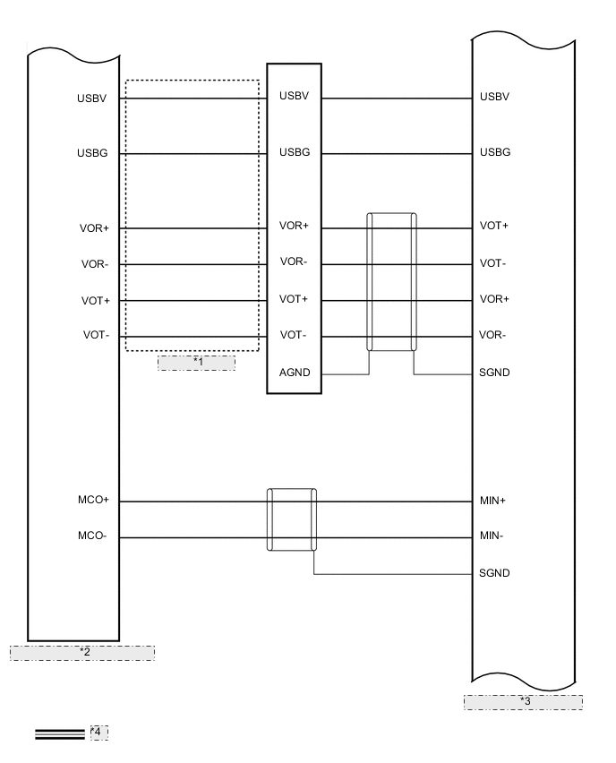
NAVIGATION SYSTEM SYSTEM DIAGRAM
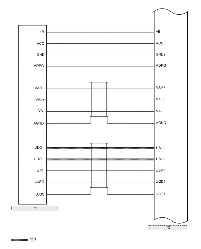
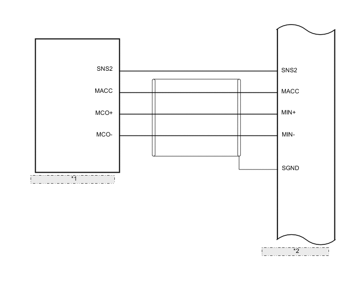
| *1 | No. 1 Stereo Jack Adapter Assembly |
| *2 | Radio Receiver Assembly |
| *3 | USB Communication Line |
| *1 | Telephone Microphone Assembly |
| *2 | Radio Receiver Assembly |
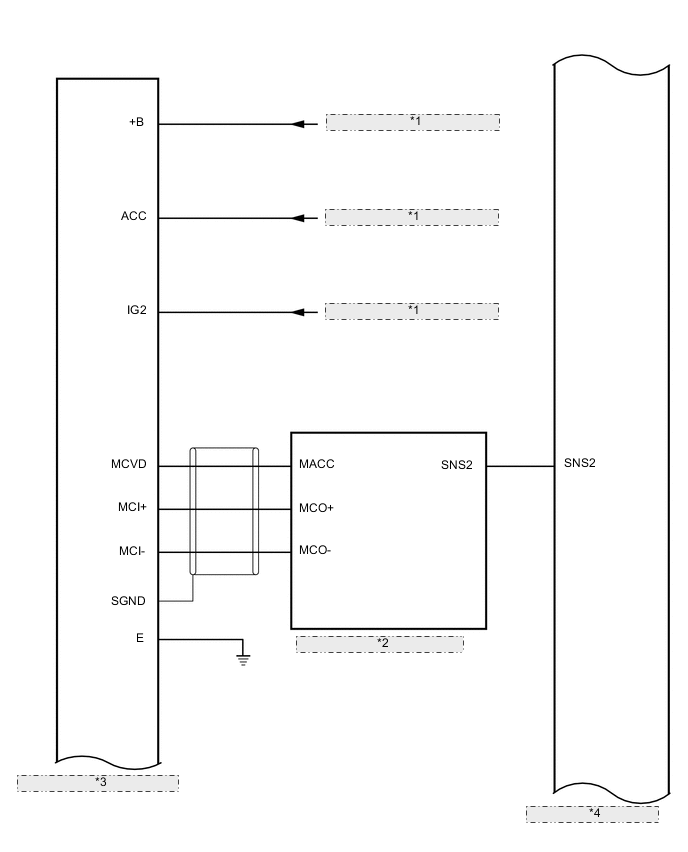
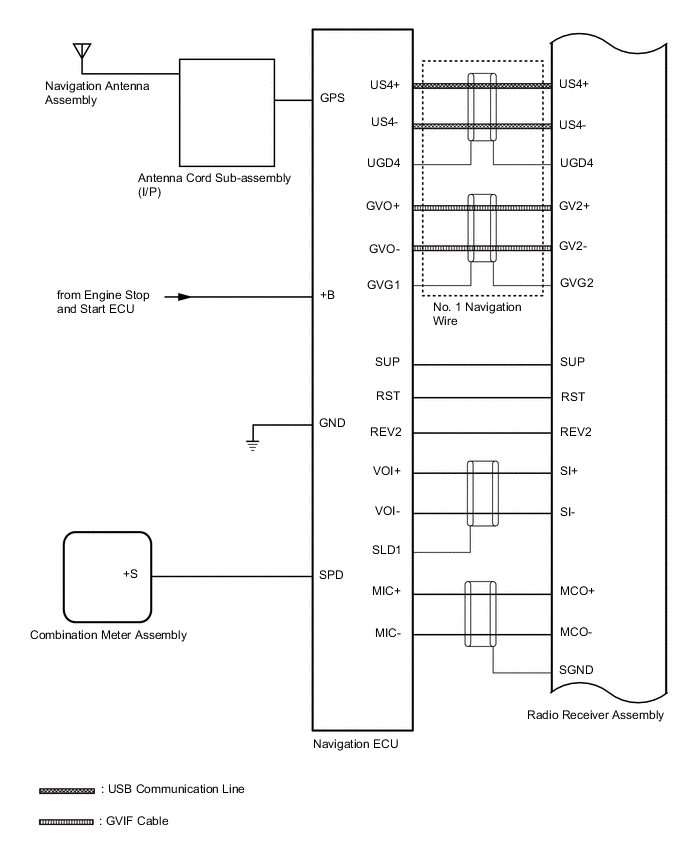
| *1 | from Engine Stop and Start ECU |
| *2 | Telephone Microphone Assembly |
| *3 | DCM (Telematics Transceiver) |
| *4 | Radio Receiver Assembly |
| *1 | Antenna Cord Sub-assembly (I/P) |
| *2 | DCM (Telematics Transceiver) |
| *3 | Radio Receiver Assembly |
| *4 | CAN Communication Line |