POWER DOOR LOCK CONTROL SYSTEM TERMINALS OF ECU
-
CHECK DRIVER SIDE JUNCTION BLOCK ASSEMBLY
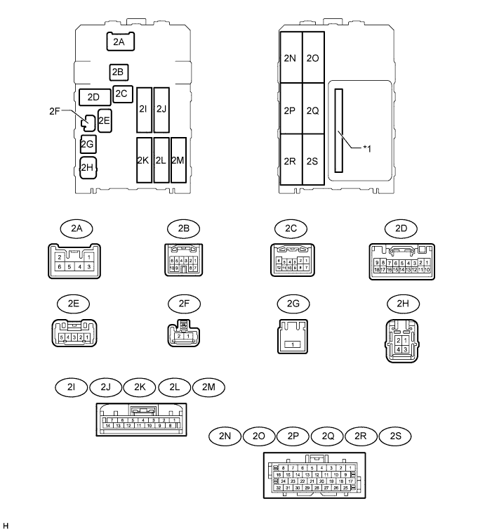
Text in Illustration *1 Integration Relay - -
-
Disconnect the 2D, 2H and 2L driver side junction block assembly connectors.
-
Measure the resistance and voltage according to the value(s) in the table below.
Terminal No. (Symbol) Wiring Color Terminal Description Condition Specified Condition 2D-9 (GND) - Body ground W-B - Body ground Ground Always Below 1 Ω 2D-18 (GND) - Body ground W-B - Body ground Ground Always Below 1 Ω 2H-4 (ALTB) - Body ground LG - Body ground Battery power supply Always 11 to 14 V 2L-12 (BECU) - Body ground L - Body ground Battery power supply Always 11 to 14 V
-
If the result is not as specified, there may be a malfunction on the wire harness side.
-
-
Reconnect the 2D, 2H and 2L driver side junction block assembly connectors.
-
Measure the voltage according to the value(s) in the table below.
Terminal No. (Symbol) Wiring Color Terminal Description Condition Specified Condition 2A-4 (L1) - Body ground L - Body ground
-
Power window regulator master switch assembly (door control switch) lock input signal
-
Driver side door key-linked lock input signal
-
Power window regulator master switch assembly (door control switch) locked
-
Driver side door key cylinder in lock position
Below 1 V
-
Power window regulator master switch assembly (door control switch) off
-
Ignition switch off, all doors closed and driver side door key cylinder in neutral position
11 to 14 V 2D-4 (UL1) - Body ground L-W - Body ground
-
Power window regulator master switch assembly (door control switch) unlock input signal
-
Driver side door key-linked unlock input signal
-
Power window regulator master switch assembly (door control switch) unlocked
-
Driver side door key cylinder in unlock position
Below 1 V
-
Power window regulator master switch assembly (door control switch) off
-
Ignition switch off, all doors closed and driver side door key cylinder in neutral position
11 to 14 V 2K-10 (ACT-) - Body ground L-Y - Body ground Door lock motor unlock drive output signal (passenger door, and rear RH door*1, *3 or rear LH door*2, *3) Power window regulator master switch assembly (door control switch) not pushed and driver side door key cylinder in neutral position Below 1 V Lock side of power window regulator master switch assembly (door control switch) pushed, or driver side door key cylinder in unlock position 11 to 14 V 2K-11 (ACT+) - Body ground L - Body ground Door lock motor lock drive output signal (passenger door, and rear RH door*1, *3 or rear LH door*2, *3) Power window regulator master switch assembly (door control switch) not pushed and driver side door key cylinder in neutral position Below 1 V Lock side of power window regulator master switch assembly (door control switch) pushed, or driver side door key cylinder in lock position 11 to 14 V 2O-27 (DCTY) - Body ground R-B - Body ground Front door courtesy light switch assembly LH*1 or RH*2 input signal Driver side door open Below 1 V Driver side door closed 11 to 14 V 2R-27 (ACT-) - Body ground L-Y - Body ground Door lock motor unlock drive output signal (driver door, and rear LH door*1, *3 or rear RH door*2, *3) Power window regulator master switch assembly (door control switch) not pushed and driver side door key cylinder in neutral position Below 1 V Lock side of power window regulator master switch assembly (door control switch) pushed, or driver side door key cylinder in unlock position 11 to 14 V 2R-28 (ACT+) - Body ground L - Body ground Door lock motor lock drive output signal (driver door, and rear LH door*1, *3 or rear RH door*2, *3) Power window regulator master switch assembly (door control switch) not pushed and driver side door key cylinder in neutral position Below 1 V Lock side of power window regulator master switch assembly (door control switch) pushed, or driver side door key cylinder in lock position 11 to 14 V
-
*1: for LHD
-
*2: for RHD
-
*3: for Double Cab
-
If the result is not as specified, the driver side junction block assembly may have a malfunction.
-
-
-
CHECK THEFT WARNING ECU ASSEMBLY (w/ Theft Deterrent System)
-
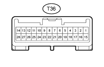
Disconnect the T36 theft warning ECU assembly connector.
-
Measure the resistance and voltage according to the value(s) in the table below.
Terminal No. (Symbol) Wiring Color Terminal Description Condition Specified Condition T36-1 (E) - Body ground B-W - Body ground Ground Always Below 1 Ω T36-4 (+B1) - Body ground L-Y - Body ground Battery power supply Always 11 to 14 V T36-14 (+B2) Body ground LG - Body ground Battery power supply Always 11 to 14 V T36-18 (IG) Body ground R-L - Body ground Ignition power supply Ignition switch off Below 1 V Ignition switch ON 11 to 14 V
-
If the result is not as specified, there may be a malfunction on the wire harness side.
-
-
Reconnect the T36 theft warning ECU assembly connector.
-
Measure the voltage according to the value(s) in the table below.
Terminal No. (Symbol) Wiring Color Terminal Description Condition Specified Condition T36-7 (CTY) - Body ground R-L - Body ground All Door courtesy switches input signal One or more doors open Below 1 V All doors closed 11 to 14 V T36-17 (SPD) - Body ground V-R - Body ground Vehicle speed input signal Driving at approximately 20 km/h (12.4 mph) Pulse generation (See waveform 1)
-
If the result is not as specified, the theft warning ECU assembly may have a malfunction.
-
-
Inspect using an oscilloscope.
Tech Tips
-
The waveform shown in the illustration is an example for reference only. Noise, chattering, etc. are not shown.
-
As the vehicle speed increases, the wavelength shortens.
-
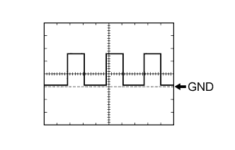
Waveform 1 (Reference)
Measurement Condition Item Content Tester Connection T36-17 (SPD) - Body ground Tool Setting 5 V/DIV., 10 msec./DIV. Condition Driving at approximately 20 km/h (12.4 mph)
-
-